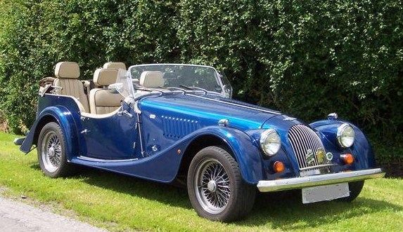
Hi Guys,
well, the excitement of driving the re-invigorated, re-juvenated Mog has ebbed enough to write up the process:
( no, not really....it's raining! )
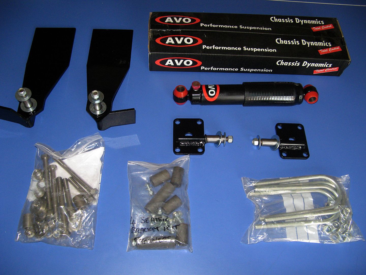
What comes in the kit?.....
There are some extra bolts and some spring bushes there that are not part of the kit but thought I may need them.
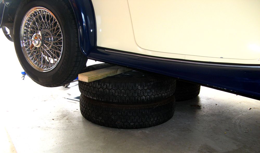
First, jack up the car and then support under the chassis giving youself plenty of room to work in ( there is a lot of lying under the car in cramped conditions ). I used two wheels either side with a wood cross member and also left the trolley jack in at the rear with the load spread between.
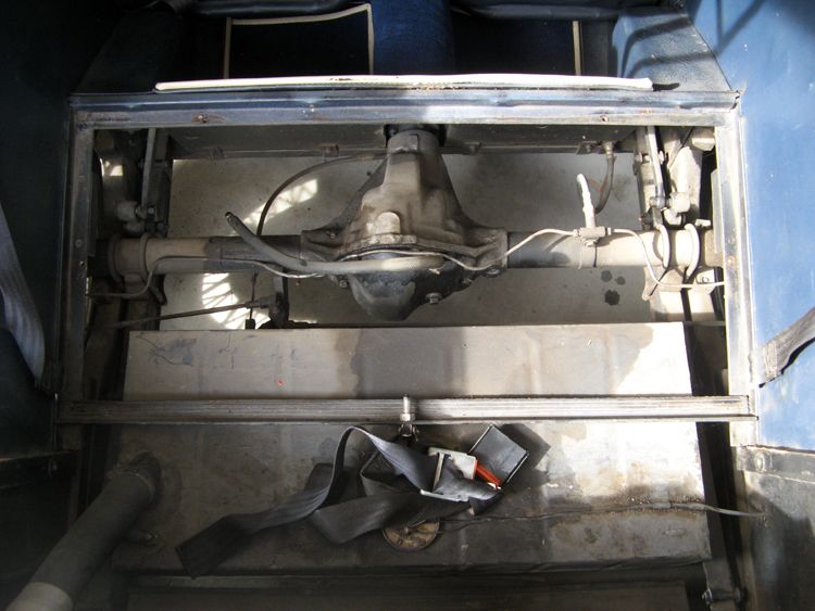
Strip out both front and rear seats, rear seat base/transmission cover, lever arm shock covers, all carpets and also remove rear wheels and spare wheel.

All is then pretty much laid bare. Undo the U bolt nuts after having first placed a wooden wedge between the underside of the spring and the lower horizontal flange of the chassis ( may need to push up the axle a bit here ).
Once U bolts have gone remove wood spacer and let spring settle towards the chassis ( It will now be resting on the bump stops on the upper horizontal componant of the chassis).
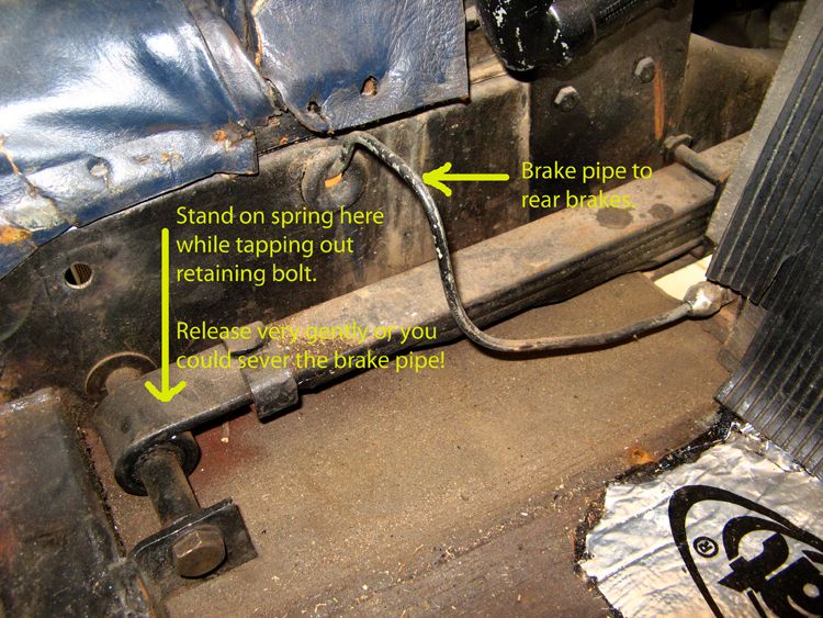
Remove the bolt from the spring eye at the front ( this is where the fun really starts

. Remove the nut on the outside of the chassis. The spring is still loaded and pressure needs to be placed on the front of the spring in order to free up the bolt. I weigh 93 Kg and was not quite heavy enough. So.....then you start a gentle up and down bounce and you have to try and synchronise the "down" movement with a leverage on the bolt head. It was during this manoeuvre that I was very grateful that the chassis was firmly supported on the extra wheels. Don't think I would have felt safe with it on axle stands.
This next pic is sequentially out of place but shows that at some stage the car was obviously used with full compliment of passengers and despite the very stiff original 7 leaf spring, there has been extensive spring excursion!

Now round to the back of the car and remove the nut from the rear spring hanger ( outside of chassis ) and the bolt. Then remove the rear eye bolt. This is fiddly with little room to work in! Push the wires aside gently as some of the older wires can get brittle with age.
With the nut removed from the eyelet bolt it is impossible to slide the bolt out through the little hole in the woodwork where the electrics go until you have rotated the whole spring inboard as far as it will go. This next pic shows the opposite side to preceeding pic:

The spring, now free can be removed through the cockpit.
I decided to remove two leaves from the pack and this necessitated buying shorter high tensile spring positioning bolts ( original on left, 45mm in middle for 6 leaves and 40mm on right for 5 leaves ), and modifying the shackles as in the pics:
Note: I also cut back the shackle bolts slightly to avoid the new telescopic shock -retaining plates being scored with any lateral movement.


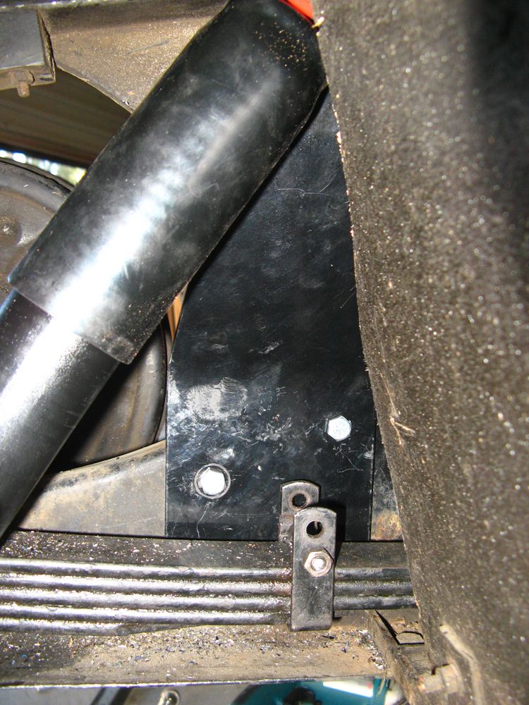
A small modification to the woodwork of the heel board is necessary before the new bracket and shock will fit. The pic shows left and right sides with right side already modified:

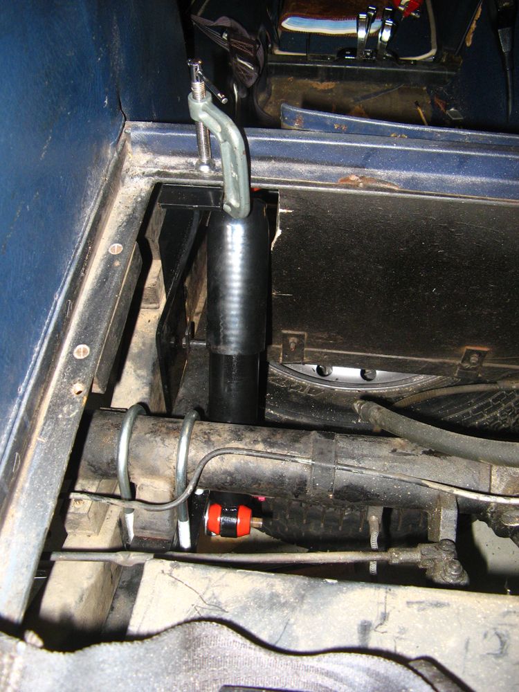
Now the new bits go in!
The new U bolts are longer than needed so need to be cut to length.
I made up a wooden template of the new 5 leaf pack. It was far easier to use this than trying to manoeuvre the spring at the same time as holding the saddle plate with shock attached. ( I also had the top mounting temporarily attached to the mounting plate just to check that everything was going to line up OK.)
I actually allowed a little extra length in case I made the decision to replace one of the leaves and revert to 6 at a later stage.


Once marked, cut U bolts to length ( placing nut on first ) and ensure that threads have been de-burred. This is so important as when you come to place those nuts on the U bolt there is precious little room to work in.....I learnt this the hard way

Place spring in position and secure the hanger and eye bolts at the rear. At this stage the fore/aft position of the spring is adjustable so that you can line-up the axle positioning pin hole with the positioning bolt in the middle of the spring.
Place U bolts over axle, spring, and through the saddle plate and secure by just engaging nuts plus their washers finger tight.
This is where I found the use of a variety of wood blocks ( including some thin pieces of plywood to add to the stack as necessary), and some clamps, extremely helpful.

Begin to tighten up the U bolt nuts ( I found this much easier to do by using a large clamp from the upper surface of the axle to the underneath of the saddle plate, squeezing up in increments and then taking up the slack each time by tightening the u bolt nuts.)
Keep checking as you go that the locating pin is well lined up with the axle positioning pin hole. At one stage I found it advantageous to temporarily secure the spring closer to its mounting bracket and to do this I just used a small twitch of wire.:

Tighten up nuts.
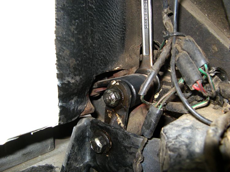
Now, to position the shock mounting bracket/plate accurately you need to locate and temporarily secure the front eye of the spring with its bolt.( more bouncing and synchronized tapping. ) You do not need at this stage to use the two sleeves on the bolt that accurately locate the spring laterally ( more on this in the final stage )
Find the best position for the mounting bracket as per the instructions with the kit, secure with clamps and mark holes. ( the advice with the kit states that the new bracket should be close to the position of the old ). I found that it was out of register such that I could use two of the existing holes in the chassis only, so had to drill two new ones ( measure multiple times, mark, measure again, then drill

)

Secure the bracket with the supplied bolts. Two could be placed with the front eye of the spring secured, for the other two the spring had to be released again. Hence the advice to not bother with the bolt sleeves yet.
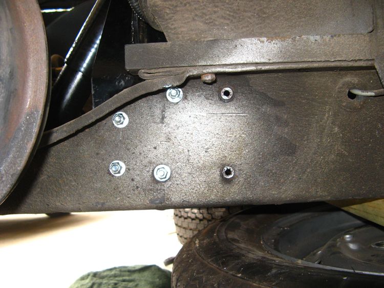
Retaining bolts viewed from outside of chassis. The two old unused holes were sealed with extra bolts.
Next secure the top of the bracket to the seat frame cross member with the supplied bolts.
We're almost there!
Now is the time to finally secure the front eye to the bracket and this time utilising the two sleeve spacers. You may need to fine tune the position of the spring fore and aft so that the eye exactly lines up with the holes in the bracket. It's bouncing time again and a synchronized tap with the hammer should see the bolt go home as per next pic:

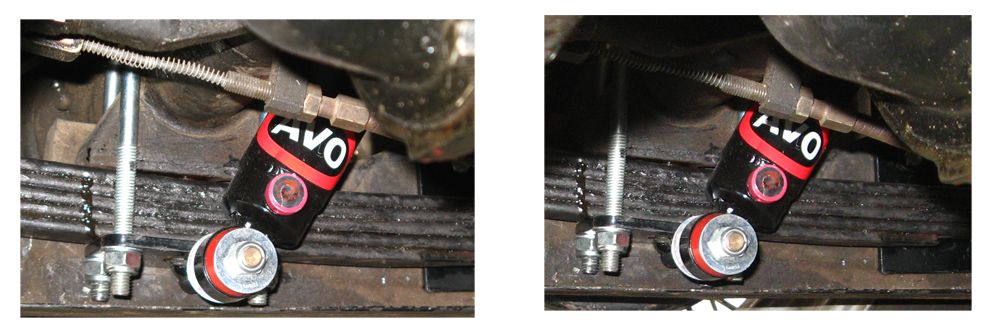
Check all bolts and tighten. Replace rear wheels and remove( in my case the supporting extra wheels ). Lower the jack and check final position of the ends of the U bolts.
Final pic shows U bolt position with car still raised on left and with wheels on ground on right:
This was one of the most enjoyable projects I have tackled, with a superb outcome. Thoroughly recommended.
Even if no-one decides to do this conversion I hope you enjoy reading about it. I've got so much from the members of this site in the short time since joining, it's a pleasure to contribute something back.

Neil.