|
Forums34
Topics48,345
Posts813,038
Members9,208
| |
Most Online1,046
Aug 24th, 2023
|
|
|
|
|
|
Joined: Oct 2016
Posts: 509 Likes: 1
 OP
OP
Talk Morgan Regular
|
2012 Plus 4 Dash Module Heater Fan Diodes
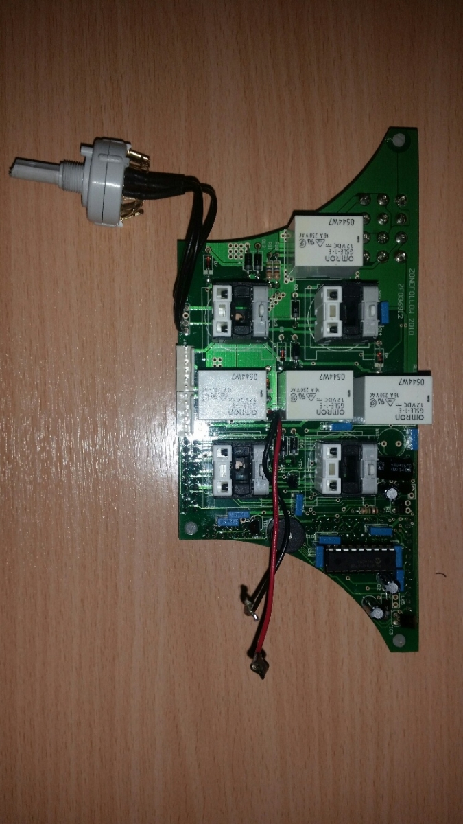
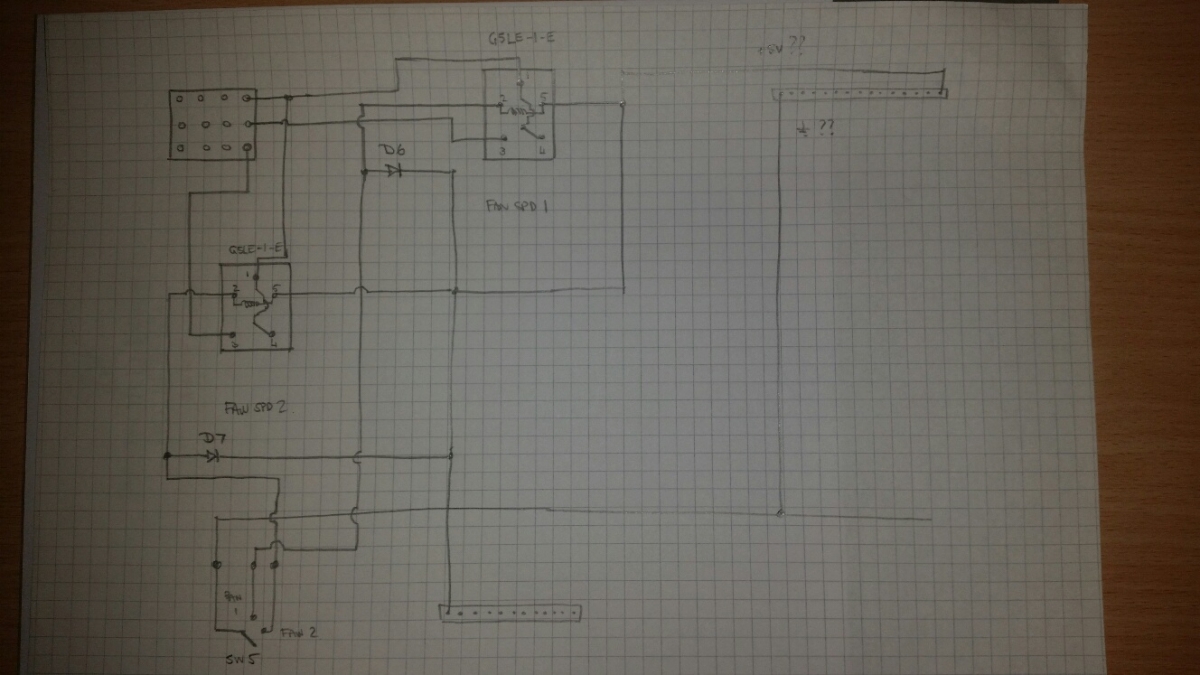
Following on from my thread from the Maintenance section, here is a pic of the board and then my sketch of the circuit - I have traced the heater fan connections as best I can with meter and Mk 1 eyeball. I have yet to check on my repaired board but as I understand it from KH, D6 and D7 are the diodes that have failed and caused the 5A fuse to blow so I lost the heater fan, speedo sensor and dash panel background lighting. These pics are of the failed board.... I have guessed that the top right 15 pin connector connections are the low current +5V and earth supplies for the relay switching are that way round - doesn't make sense otherwise (need to check on the loom diagrams later though).
No warranty given if you mess about with your board... top right is a microcontroller with embedded software, and behind are a pair that look a bit like FGPA chips so it's a scary place to wield a soldering iron!
|
|
|
|
|
Joined: Oct 2016
Posts: 509 Likes: 1
Talk Morgan Regular
|
|
OP
Talk Morgan Regular
Joined: Oct 2016
Posts: 509 Likes: 1 |
Sorry that was not clever was it - you need to rotate the first image 90 degrees anti clockwise to get the equivalent of the diagram
Nick
|
|
|
|
|
Joined: Aug 2010
Posts: 5,223 Likes: 123
Charter Member
|
|
Charter Member
Joined: Aug 2010
Posts: 5,223 Likes: 123 |
Those smaller diodes look a little under size.
Good luck with the detective work.
Would love to know what the marking on the chip is - curiosity and all that.
Last edited by Paul F; 14/11/17 10:01 PM.
|
|
|
|
|
Joined: Jan 2012
Posts: 14,976 Likes: 1
Member of the Inner Circle
|
|
Member of the Inner Circle
Joined: Jan 2012
Posts: 14,976 Likes: 1 |
Richard
1976 4/4 4 Seater
|
|
|
|
|
Joined: Oct 2016
Posts: 509 Likes: 1
Talk Morgan Regular
|
|
OP
Talk Morgan Regular
Joined: Oct 2016
Posts: 509 Likes: 1 |
Well this is now my backup board so I am using it to educate myself. And hopefully repair as a spare. I'll be looking at other parts of the board in due course - easy bits first like hazards and rear fog light.
The IC top right is a PIC16F818-I/P microcontroller. I am wondering if it is a controller for the air conditioning given it's position on the board. My other thought was speedo sensor but I understand that is a box in the engine bay by the main ECU.
|
|
|
|
|
Joined: Aug 2010
Posts: 5,223 Likes: 123
Charter Member
|
|
Charter Member
Joined: Aug 2010
Posts: 5,223 Likes: 123 |
The IC top right is a PIC16F818-I/P microcontroller. I am wondering if it is a controller for the air conditioning given it's position on the board. My other thought was speedo sensor but I understand that is a box in the engine bay by the main ECU.
Air Conditioning sounds feasible. Possibly to manage a start sequence?
Paul
Costock, UK
2014 4/4 Rolls Royce Garnet Red
Disco 5
Teddy - 17h1 Irish Draught cross
|
|
|
|
|
Joined: May 2012
Posts: 1,639 Likes: 20
Talk Morgan Enthusiast
|
|
Talk Morgan Enthusiast
Joined: May 2012
Posts: 1,639 Likes: 20 |
A wild guess but I believe these cars might have an early type of can-bus system for instrumentation etc. The pic might be used for that? Good luck Nick 
Roger
2011 Plus 4
|
|
|
|
|
Joined: Apr 2014
Posts: 3,547 Likes: 4
Talk Morgan Addict
|
|
Talk Morgan Addict
Joined: Apr 2014
Posts: 3,547 Likes: 4 |
Those are the relay flyback diodes, the data sheet on the G5LE-1-E relays state around about 33.3mA current is present in the continuous draw to hold the relay on.
As long as the replacement diode can handle that (when it releases the current flows away through the diode to save having a voltage spike) it should be fine.
I think I'll be swapping mine out while it is still working I'll do the same for all the relay diodes.
Cheers for the info.
Mark - No Longer driving Archie the Old English Sheep Mog........... 2010 Roadster 3.0 V6 (S3) 
|
|
|
|
|