Update 44 - ECU swap and a spot of loomingSo I've got a couple of clear days to focus on one of the jobs that I was not sure was going to work out.... the ECU swap is easy but given we have integrated the previously installed Fully Assembled ECU harness into the Race Technology digital dash and data logger I need to add in the extra wiring to get what we need to run the Injection system.
If you were doing this fresh you would not have this problem - it's just that I'm updating a prior install.... additionally I need enough stuff left to make up the ECU loom to put into Woodstock.
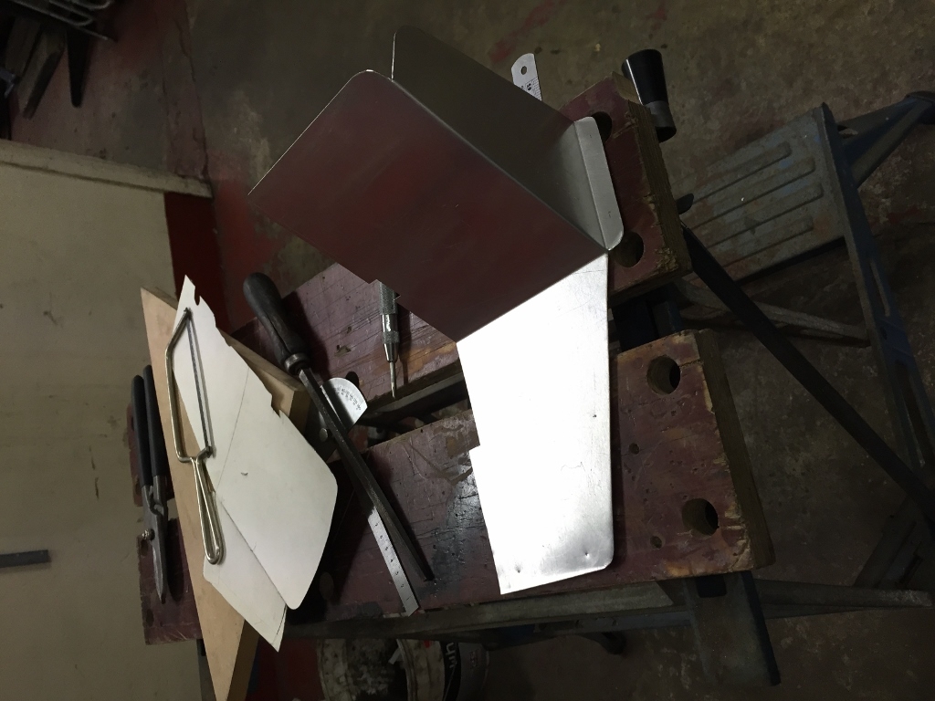
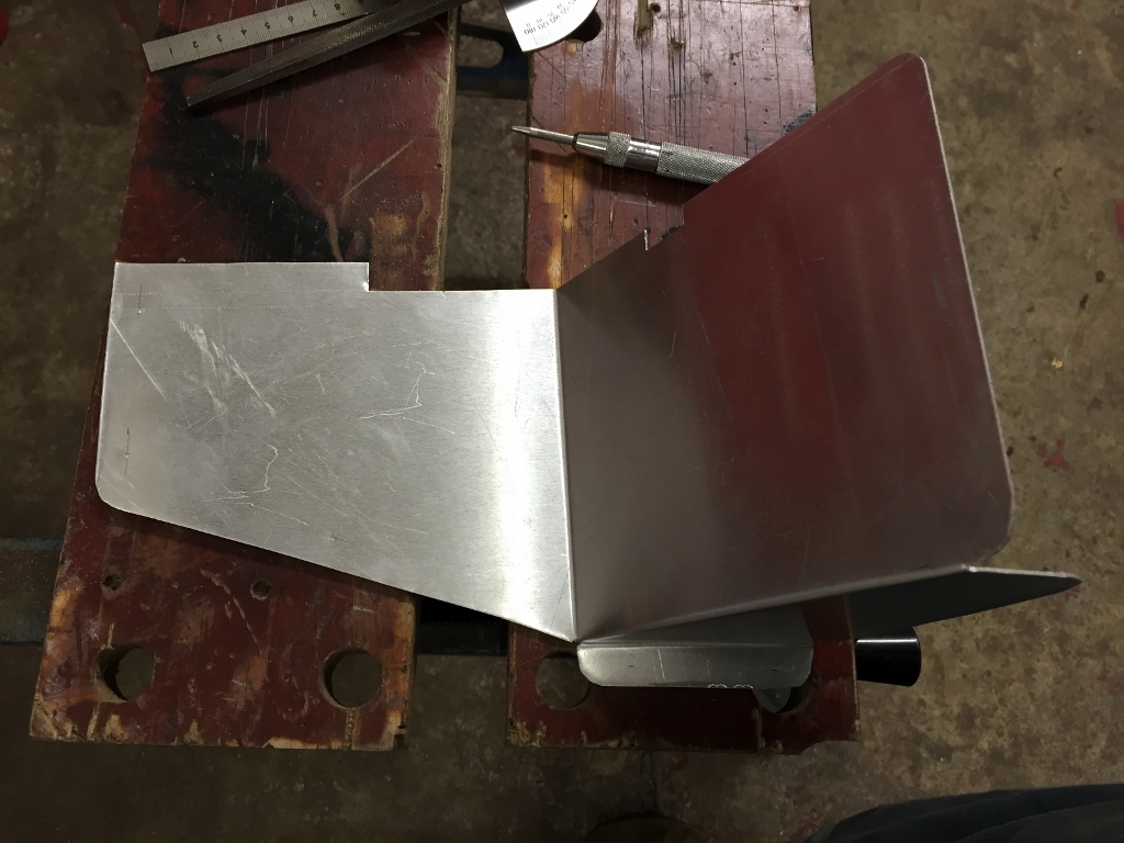
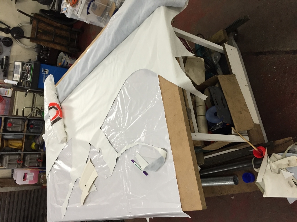
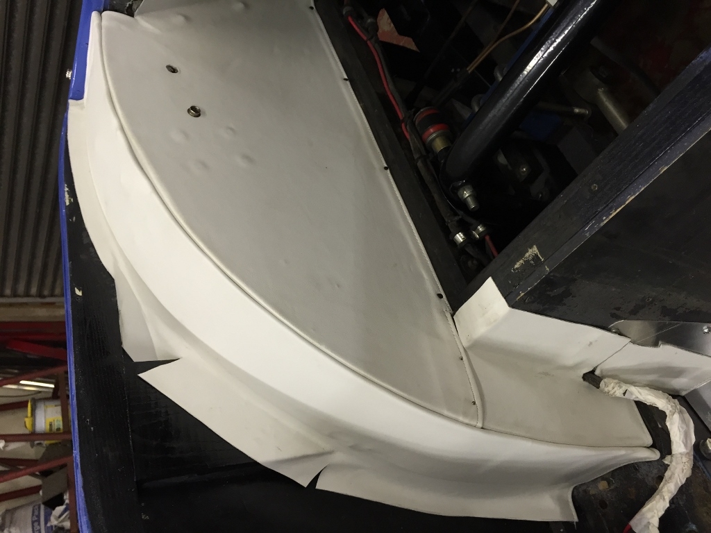
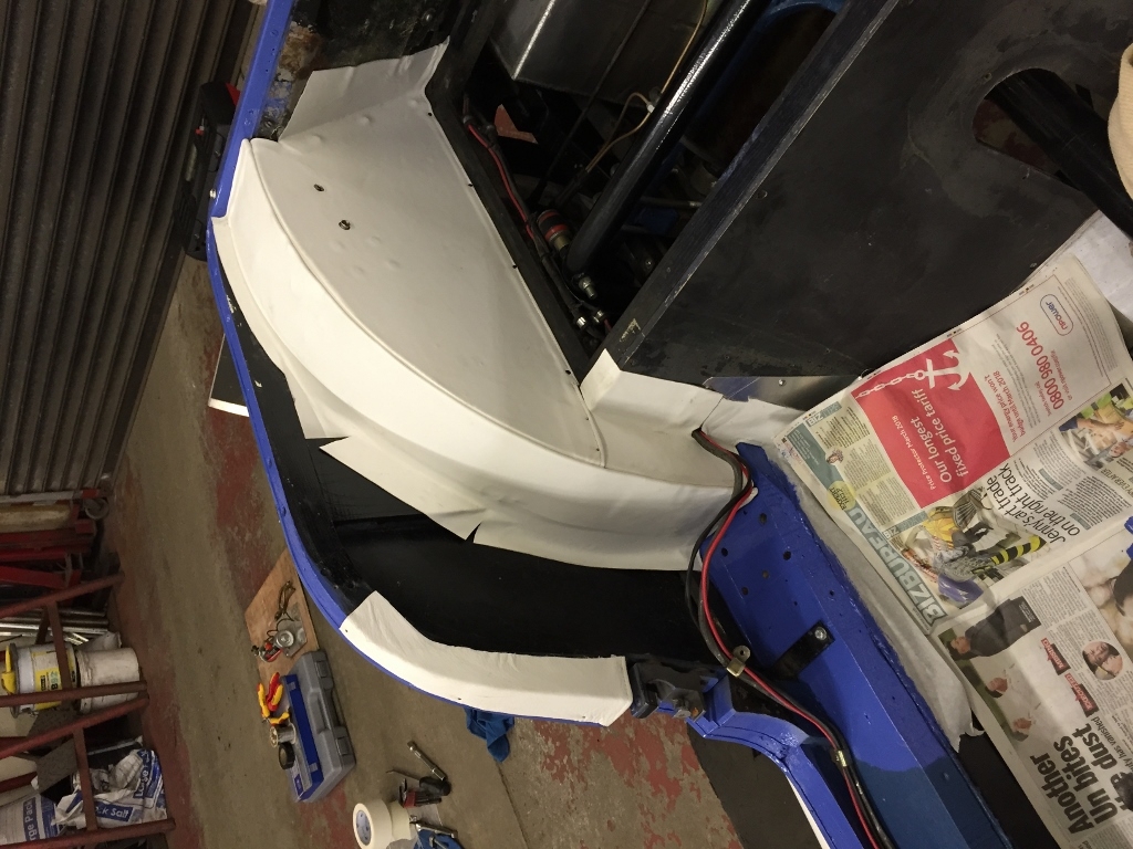
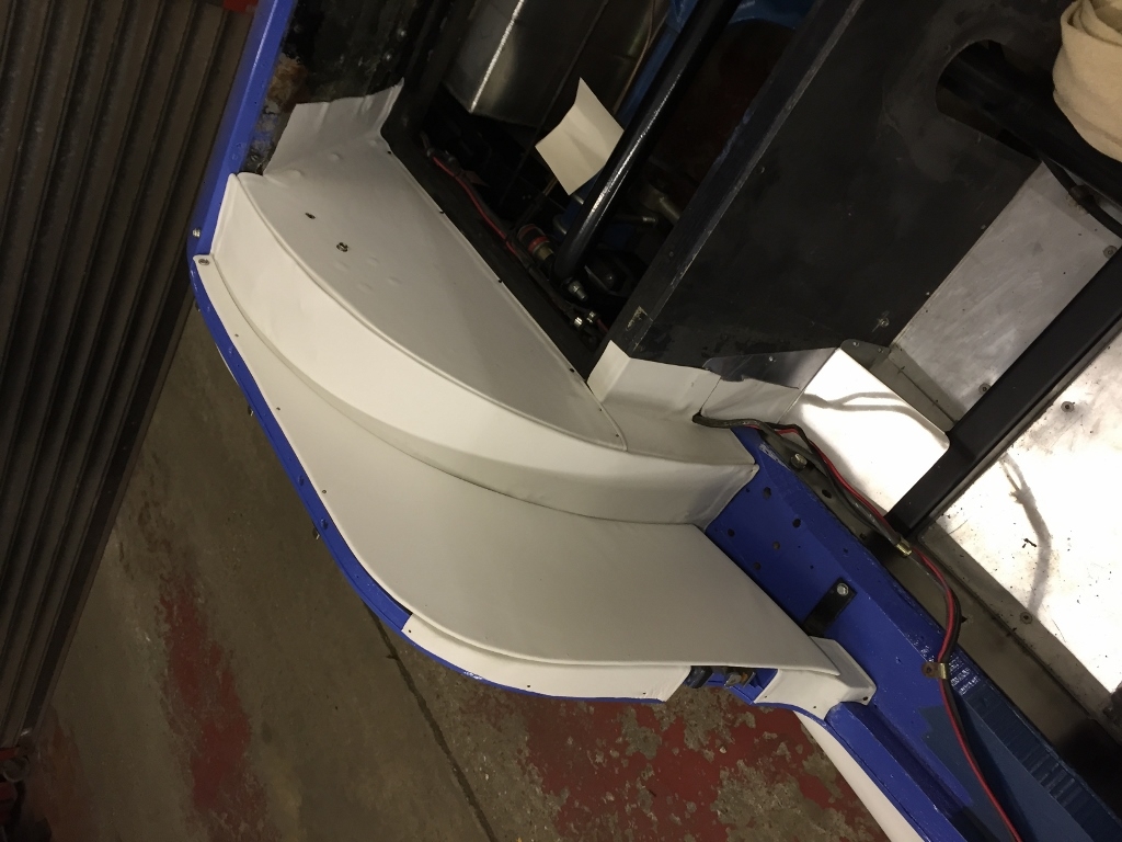
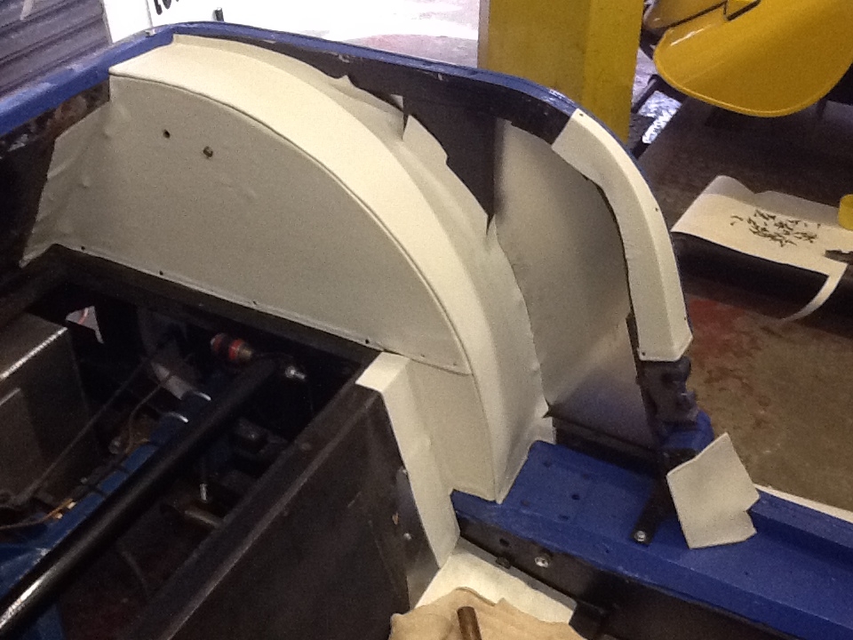
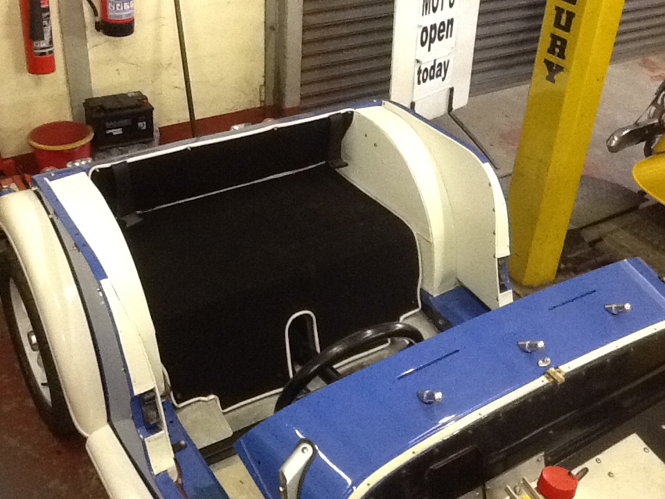
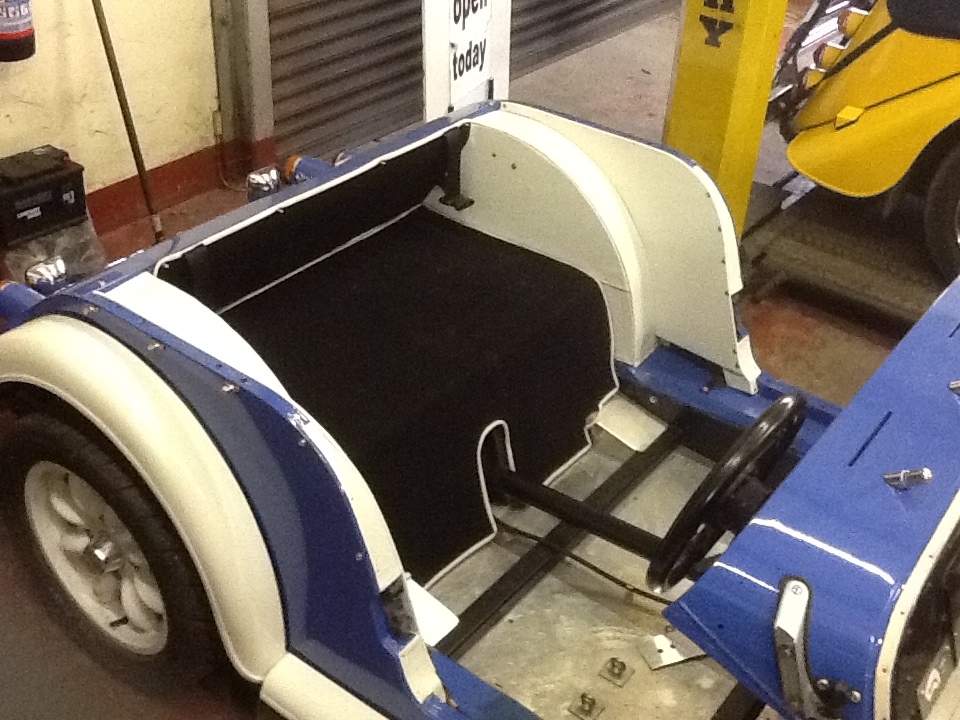
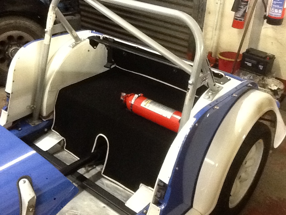
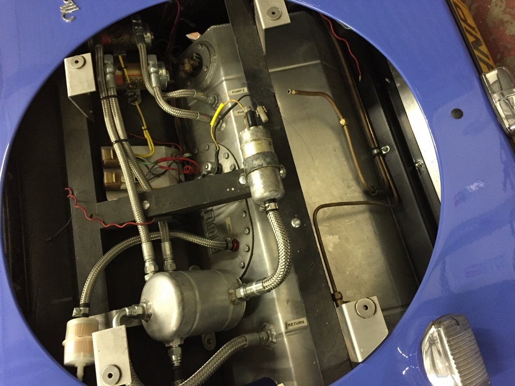
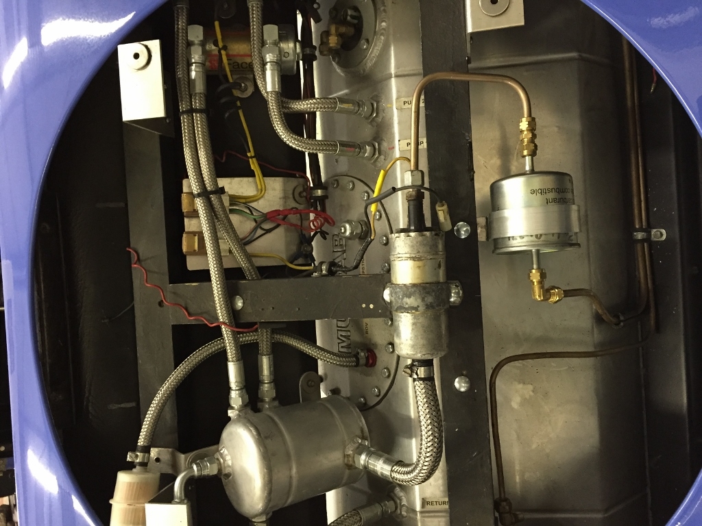
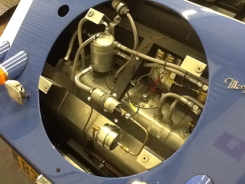
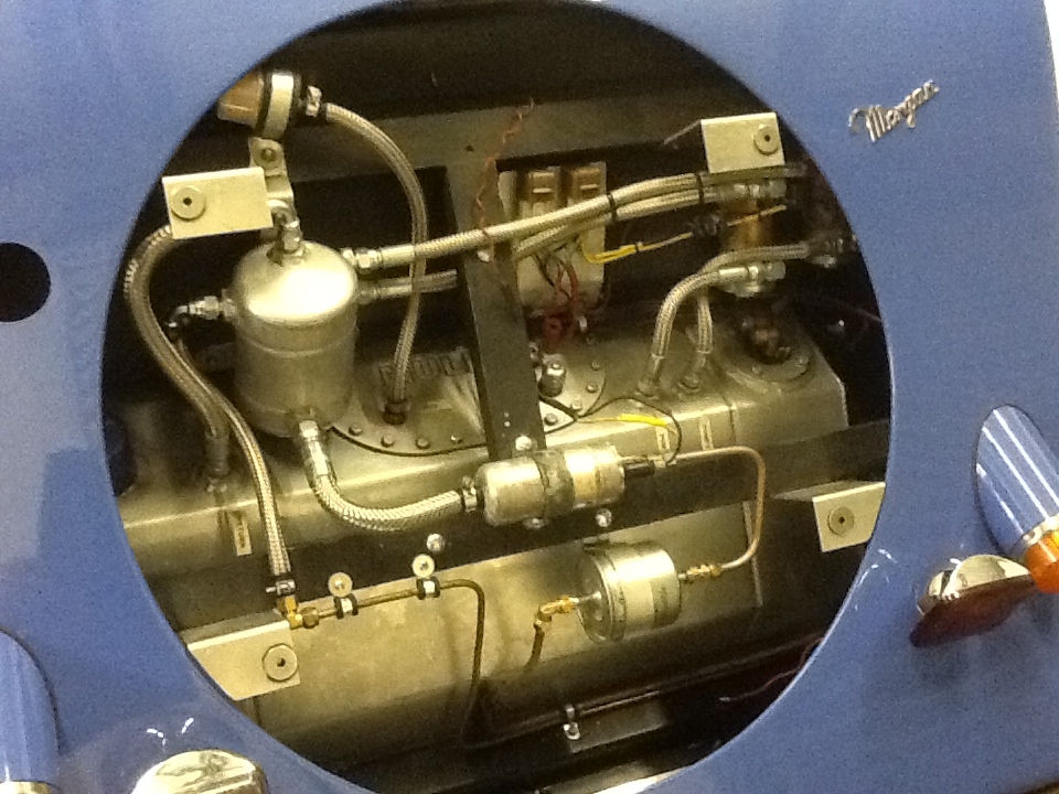
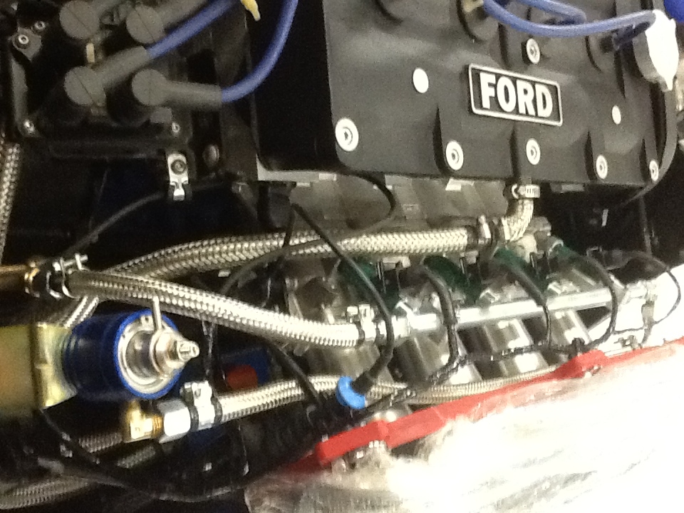
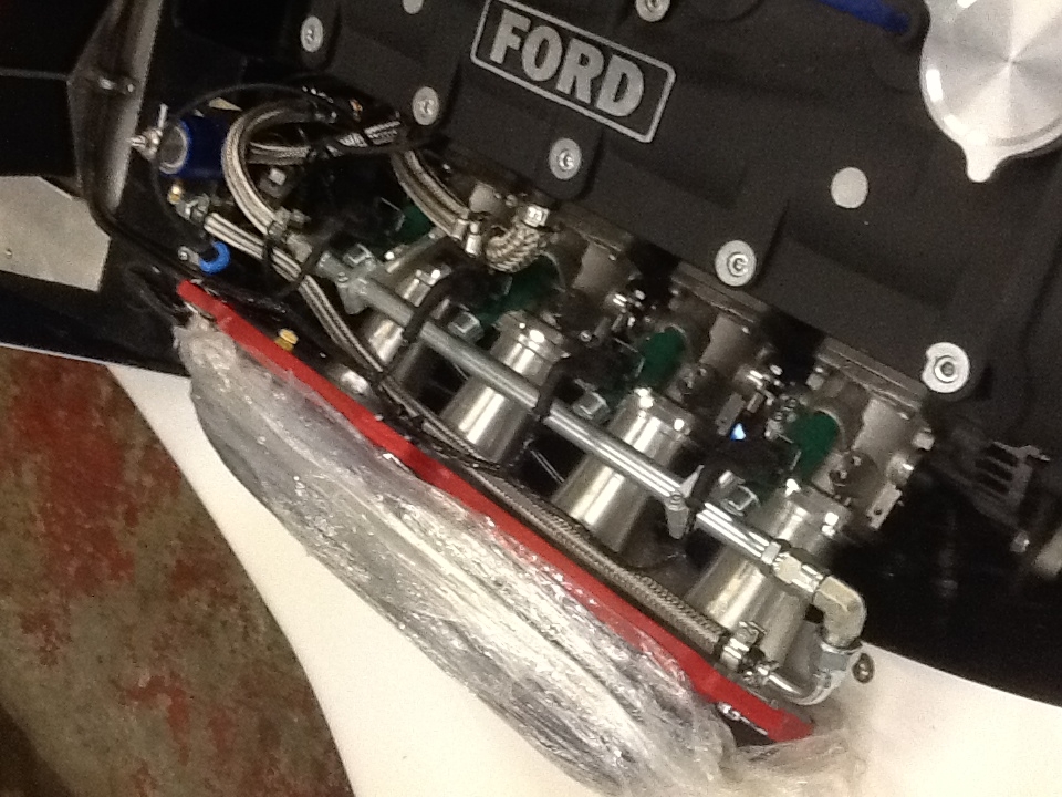
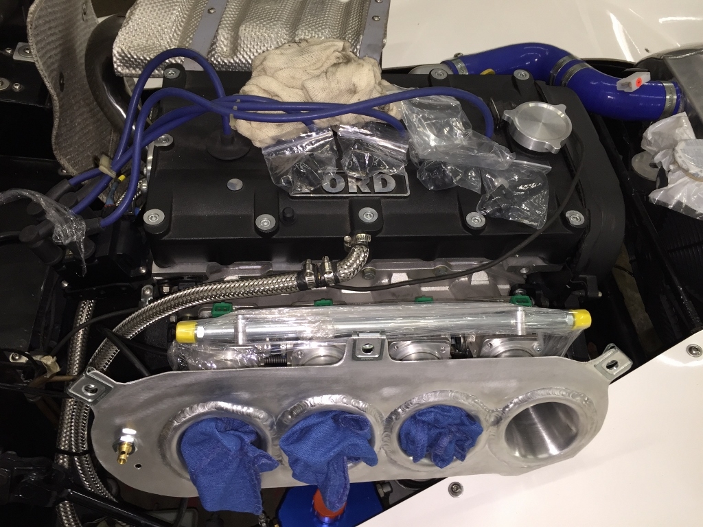
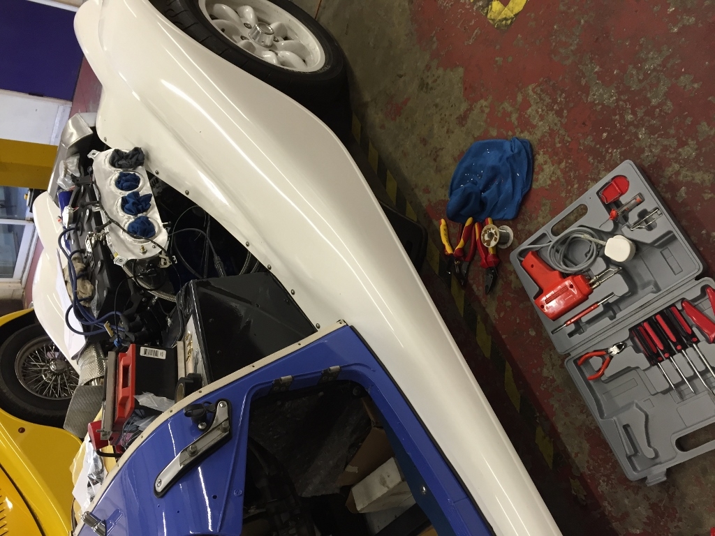
So in the car is the set-up in this image

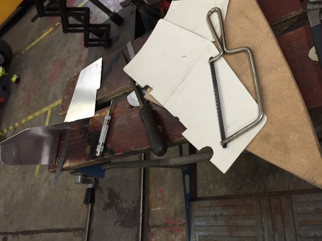
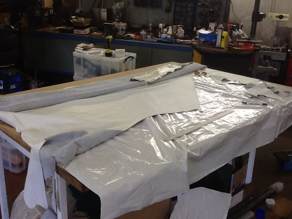
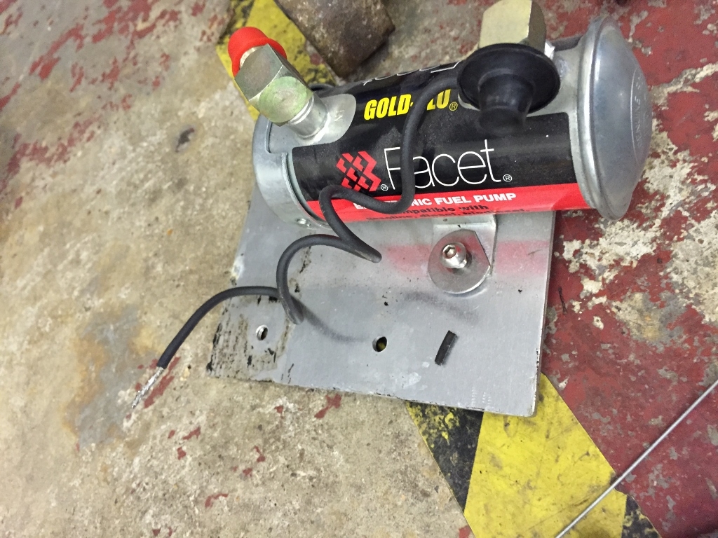
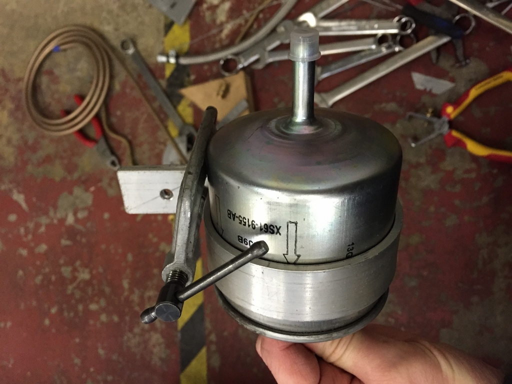
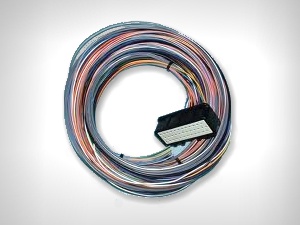
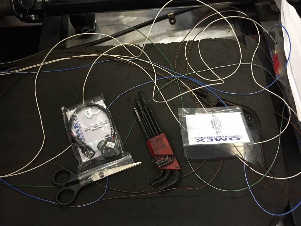
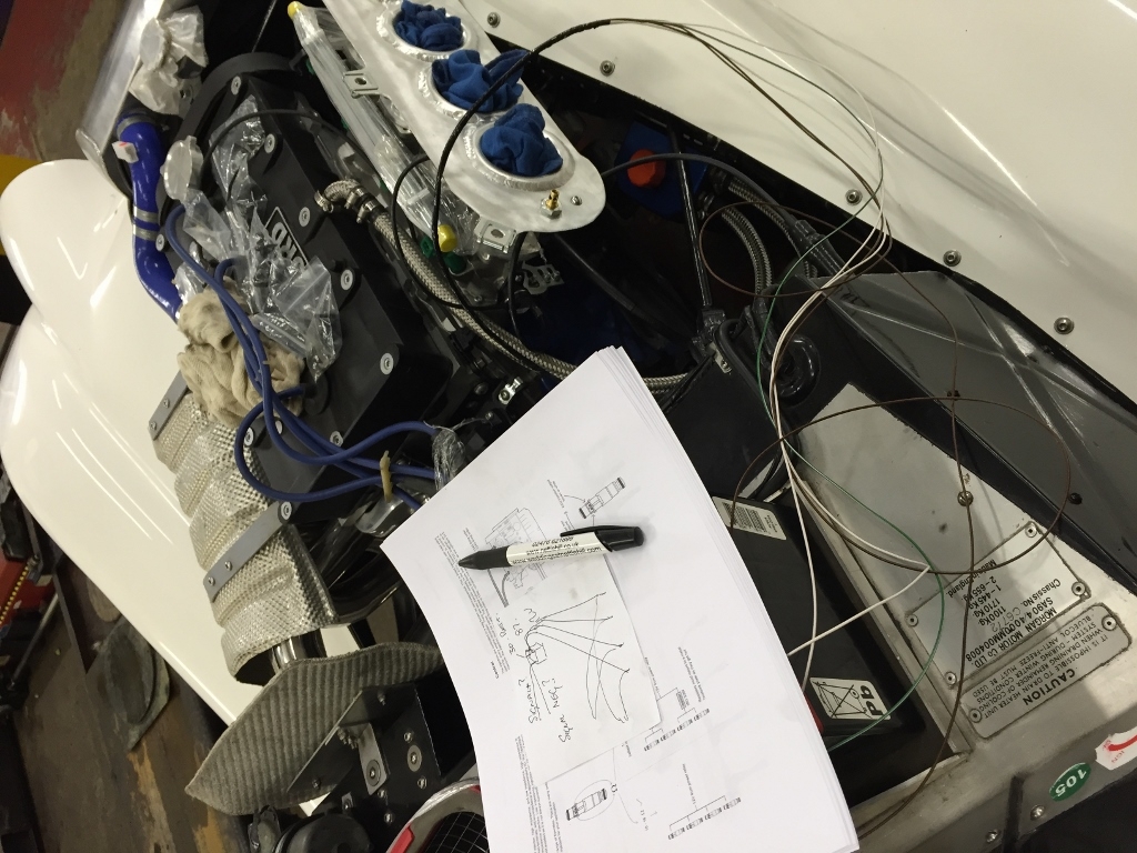
and what I have purchased is the following with the idea to "rob" of this partially assembled complete loom what I need to integrate into the package above - simples right!!
After some investigation of the Omex 200 and 600 manuals online - both have common pin-outs - result so just need to get the extra wires in.
The Omex ECU plug comes like the following
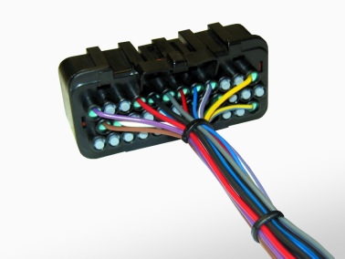
The un-used pin holes come with rubber bungs into them - having got my hands on the plug these come out pretty easy... so now what to put in them...
Going over to the new partially assembled loom I pulled off the white centre cover from the front side - you can see it above - this is only held in place through tab friction fit so it should come off easily.
Next up - I wonder if the pins come out easily - I can't imagine you can't get them out - what if you made a mistake during assembly - you'd want to get them out.
After a bit of googling one night I found on a fiat web-forum a guy asking the same question and a response which suggested a small jewellers screwdriver down next to the pin releases it.
So armed with a very very small set of screwdrivers I gingerly slotted it down in what looked like a recess below the pin - with a small click the pin was released and I could easily pull it out of the ECU socket housing - looking closer the pins have a tiny sprung spur which clicks into place inside the housing.
So, what extra wires do I need - the Omex 200 was designed to run 3D ignition for carb engines, it takes RPM (so crank position sensor is already in place), Throttle position (so the TPS is already in place) and engine temp (so engine temp is already in place) and finally the coil wiring is already there. To run injection I need the Injector drivers (which come paired) and Intake air temp sensor. The Omex 600 is also capable of controlling the pre-charging of the high pressure fuel system (2 seconds burst on first stage ignition) and the rad fan (so you could replace the otter switch system).
So I stripped these wires out of the loom - they won't be needed in Woodstock as the Omex 200 system does not need them.
You get this lot to install under the dash
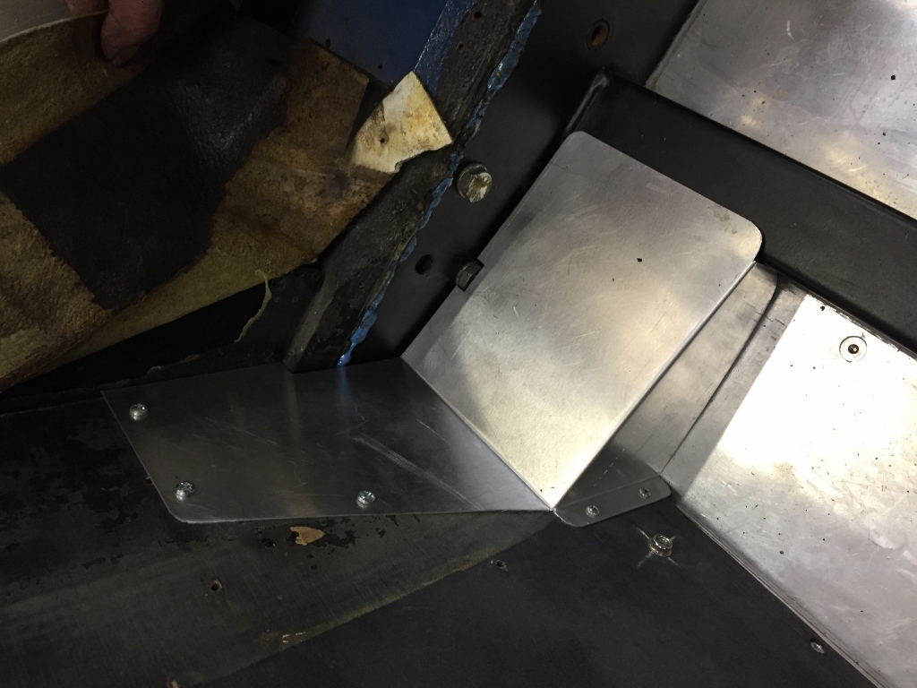
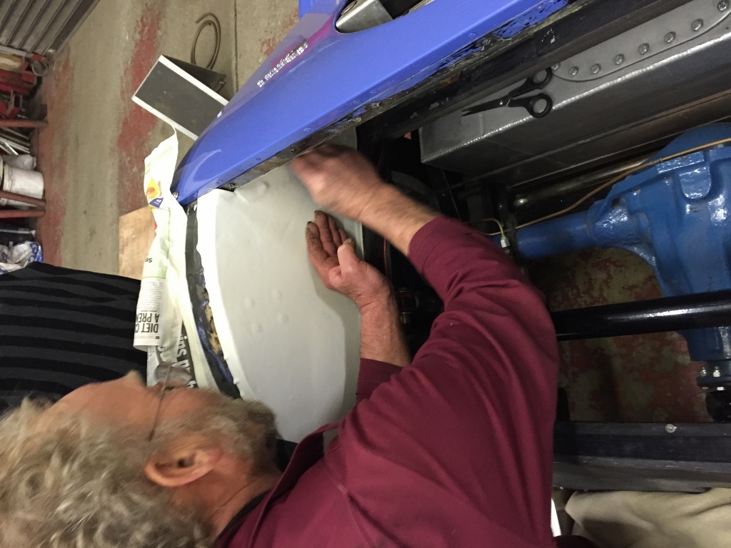
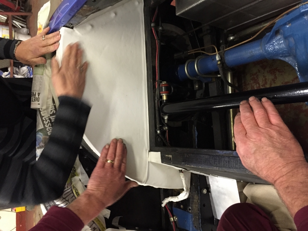
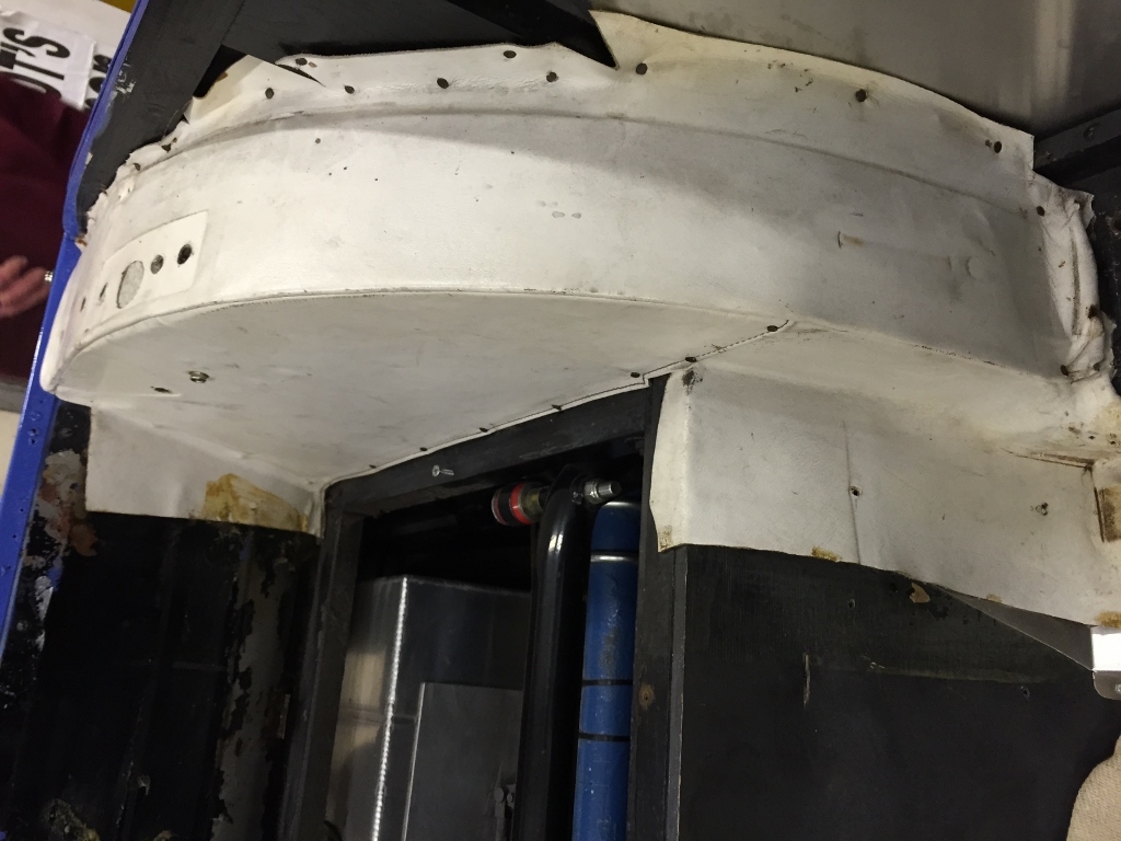
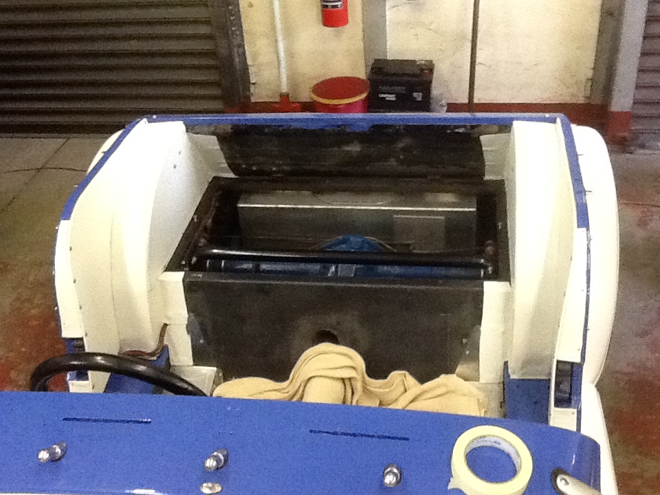
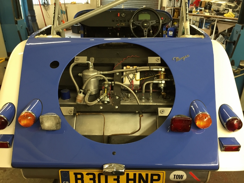
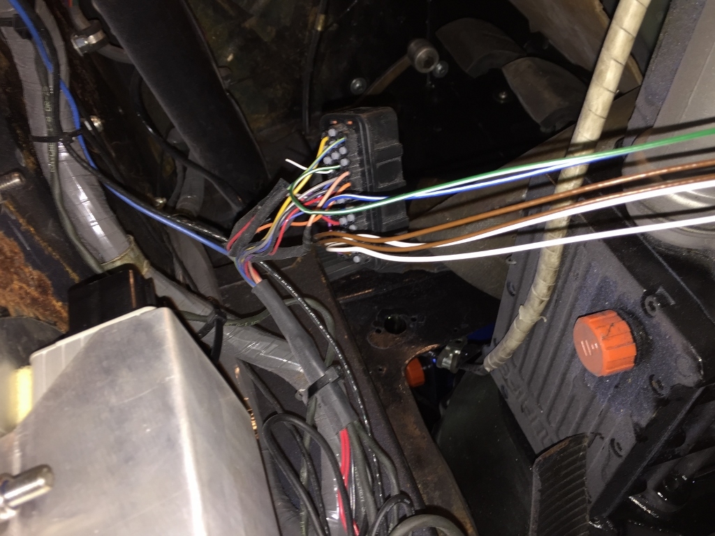
For us the ECU is held to the underside of the bulkhead by a foam lined aluminium holder - so swapping over is pretty easy.. you can just see the holder in the bottom left corner of this photo.. and you can also see where I have slotted in the additional wires into the ECU plug already in the car - this is really simple - you just thread the pins through the right way up and they just slot in.
Moving onto the sensors - before running the wires into the engine bay - lets work out where everything needs to go.. lets start with the easy one - the Intake Air Temp sensor.
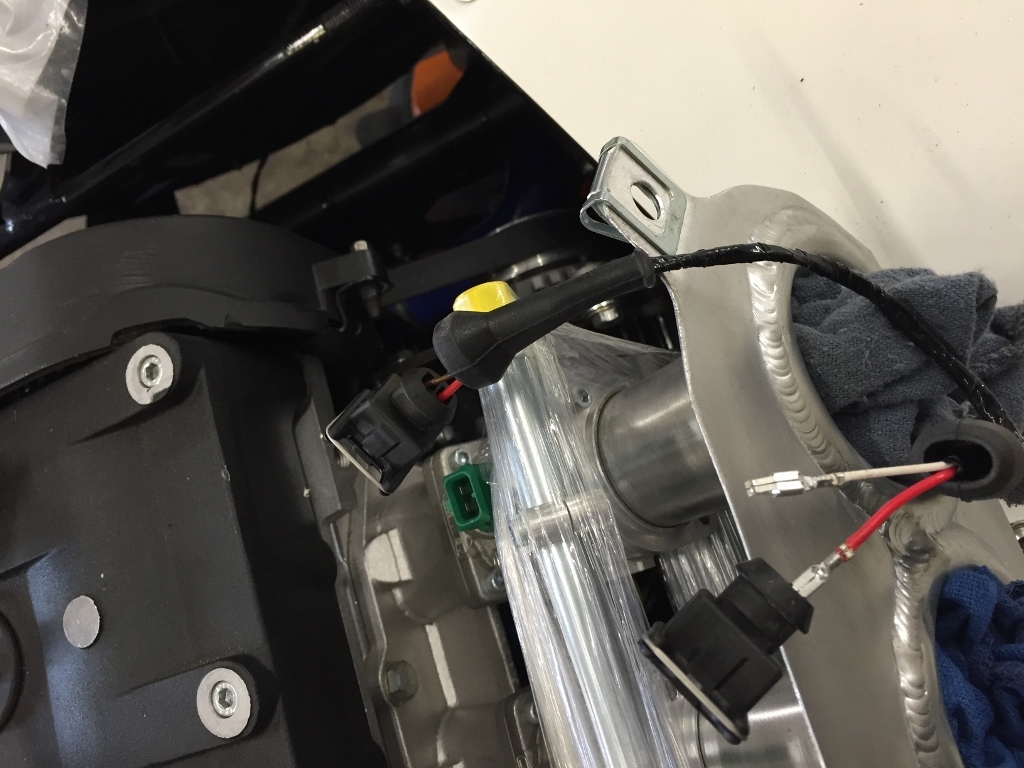
It needs to go ideally in the air-box (or within the filter) but without disturbing the air-flow. So for us the back-plate of the filter is slightly off-set to the rear of the car so there is plenty of room to put this to the left of the rear most intake. A 10mm hole and its just a case of using a 1/2 nut (which did not come with the sensor) to secure it. Remember not to do it up too tight as it's very fragile and also to use some thread lock - you don't want a nut finding its way into the intake!!
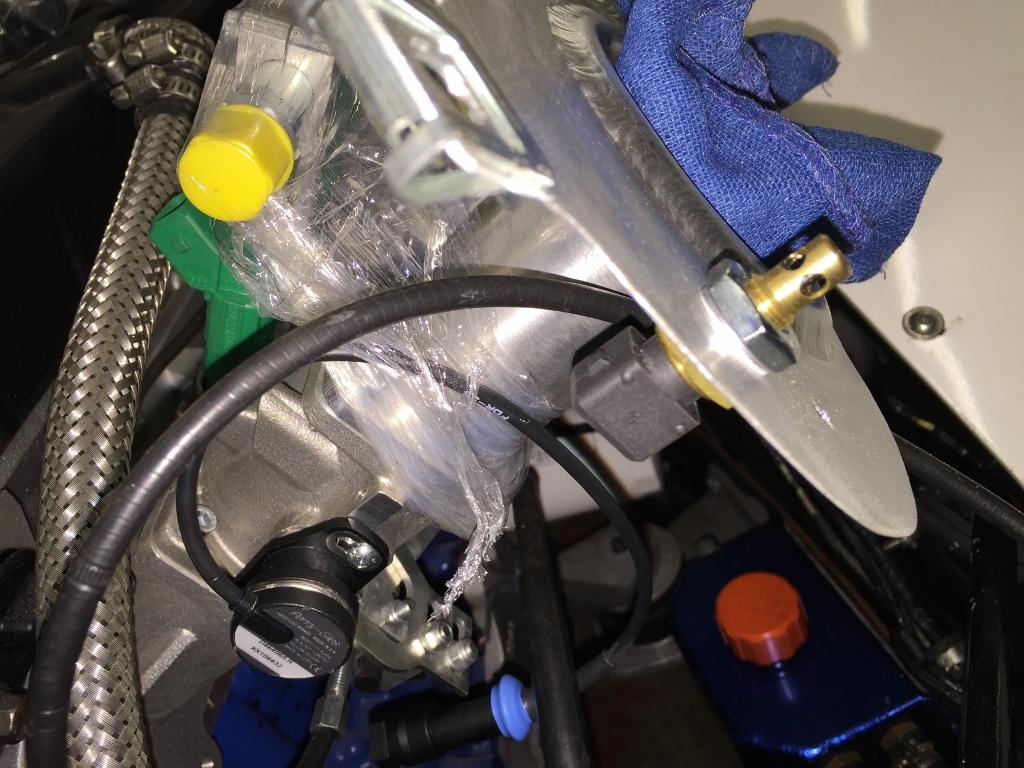
You can also see from this photo I have already installed the Throttle Position sensor - one difference between the carb install and the injection set-up is that the TPS sensors have different plugs!! so I need to cut and join in the correct plug - handily I've ended up slightly awash with sensors so I have a spare two pin plug kit in the spares pack....
I'll come back to that when I crack out the soldering iron - for now there is still the small matter of the injector harness.....
One of the down-sides of doing a custom build is that you don't know all the variables in advance - you also can't always order a part off the shelf to do what you need... in this case - earlier I'd integrated the injector driver signal wires into the ECU plug - but these are only the signal cables - we still need to supply 12v to the second pin.
So out comes the injection plug boots x 4
Having studied the instructions and looked at how this was going to work - I need to run a relay swittched 12v to the injectors - I've decided to run four 12v feeds off of a core relay rather than daisy chain them. So I need to get the feeds run in.
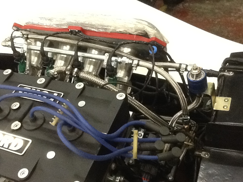
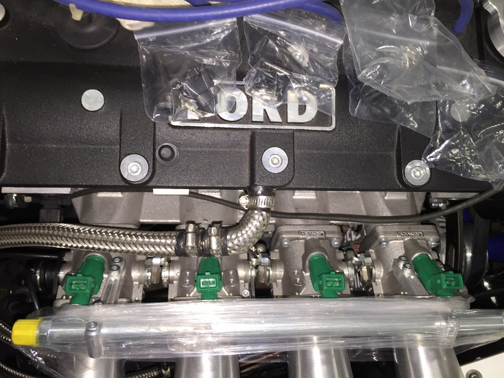
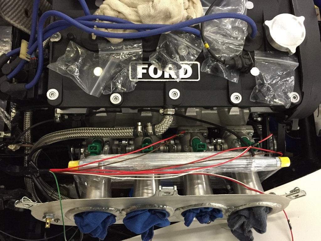
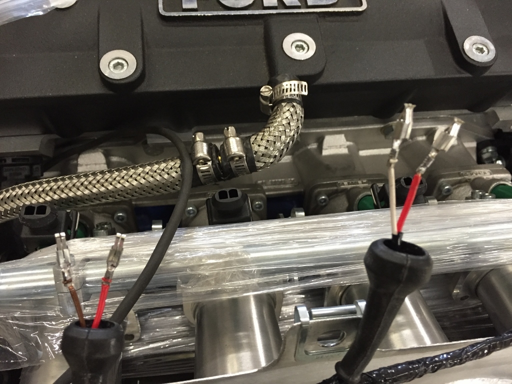
You can see in the photo below the pairings - the Brown's and Whites are the Omex injector signal wires and the Red's are the 12v feeds.... I've paired them up with small insulation tape loop and used loom tape to create an initial start of a loom where the cables run through the bulkhead - I've also decided to run the loom on the inside of the car from N/S to O/S before coming into engine bay thereby saving any exposure to the heat that might be in the engine bay behind the exhausts.
Having positioned everything out comes the soldering iron and special crimping pliers for the pins.
Here are a couple up close - personally I preferred to use the soldering pen rather than the gun style. When actually soldering them I had a ft square board which I put on top of the engine which I could tape the wires to to hold them steady. Remember to put the boots on before you solder it all up.
Below you can see the first plug nearly assembled and the start of the loom tape to keep everything neat.
So going through all four injectors and looming it all up you get a nice finished job.
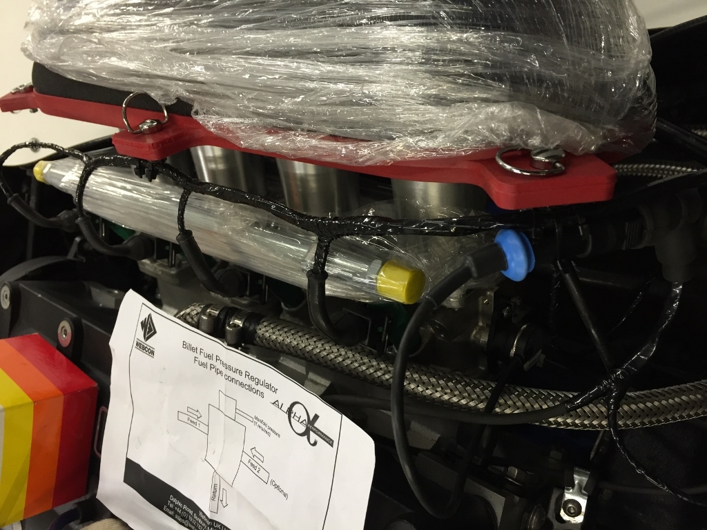
You can also see in this picture the Air temp wiring and the throttle position sensor wiring. The splice you can see there is the common sensor return cable that goes to both (grey).
All done... next time back in side for some trimming work....