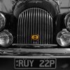
Today I made a start on Mr Bumble's kingpins. First here's all the stuff on the bench.

I used some thick leather, doubled over as a buffer and the spinners came off much easier than the old earless spinners.

Here's my lifting beam under the cross tube and held by axle stands.

This next photo is quite important. The Caparo calipers don't use split pins, they have dumb bell like retainers which can be drifted out either way, but are held in place by "traditional" spring clips. I managed to damage one of the spring clips when removing, but have some new MGB clips in stock. However, although they look the same, the MGB items are very slightly narrower,so not really suitable as this would allow the pins to move slightly sideways. They would do as a short term fix. I rang BHM, but they don't carry the clips in stock, and have not supplied any. They don't come with new pads by the way. So I rang Rutters, but got the same response. So I've contacted Caparo direct, but am not hopeful as these parts are pence in value even though they are safety critical. I'm presently looking into an alternative source so will let you know what turns up.
The other important thing to note is that the pads have a lip on the outside edge caused by the pads slightly overlapping the outer edge of the disc. I've filed the lip away, but it will recur as the pad and disc don't exactly align!
These pads are exactly the same as on my Roadster which has the earlier Lockheed calipers.

I hung the caliper out of the way on a cable tie, after checking that none of the pistons were sticking.
Note that the flexihose is armoured, but also has a clear plastic cover. The plastic cover has been worn through in one place, which looks like it may have rubbed on the tyre or rim. So check yours...... This has not damaged the armoured braiding. When I fitted the brake reaction bars, I added a rubber hose buffer because the hose does touch the reaction bars. Note also that the caliper has two bleed screws.

Here's the split pin, just emerging at "two thirty" - o'clock. Needle nosed pliers are essential. The nut was finger tight, which is usual.

Here's the bare stub. The nut visible at 9 o'clock is the sensor I've spoken about before. A cable runs from the back of this, into the loom at a multi plug under the wing.
Note the end of the rack. The boot is only held on by a cable tie, so it's very easy to pop the boot off and check the state of the lubrication. Pack a bit of grease in the end if it's dry. If you put it on 'right lock', the rack will take the grease inside when you straighten up.

The S shape cable (below) is the sensor cable, which is threaded into the backplate and secured by the nut in the earlier photo.

This is the back of the disc (with fresh paint). Note the evenly spaced bolts and nuts. I believe these are to trigger the sensor, and I wonder if there will be this many on the other side.

And here we are with track rod end off, lower reaction bar removed, and lowering rods fitted ready. I've also cracked the top lube bolt, and bottom kingpin nut. Note that this stub axle is very sticky on turning and is grabbing the main spring, even though it has MMC steering bearings. When I get the stub off I will post pictures of the MMC bearing next to the Mulfab bearing.

I've been cleaning up as I've gone along, but be in no doubt that this job is incredibly messy. Grease everywhere......

Anyway, after a leisurely day, time for a break.










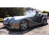

 Look forward to the next instalment!!