Click here to return to the home page.
Image of a road.
Who's Online Now
6 members (trendstone, IcePack, Ulfulf, Oskar, Mybluemog, Ian Wegg), 244 guests, and 40 robots.
Key: Admin, Global Mod, Mod
Top Posters(30 Days)
John V6 83
+8Rich 69
DaveW 67
Luddite 57
Newest Members
Ulfulf, Wilfried, Classic-Line, BrunswickGreen44, Franco Morgan
9,203 Registered Users
Newest Topics
Goggle eyed
by Roady - 19/07/25 06:16 PM
FOR SALE AERO8 series 1 WHEELS
by t50 - 19/07/25 12:07 PM
Lions Tour
by OZ 4/4 - 19/07/25 11:55 AM
Morgan rebuild on Facebook
by TBM - 19/07/25 10:50 AM
Ride Comfort & Tyre Age – Plus 4 Duratec
by Nick B - 19/07/25 10:22 AM
Super3 Accessory Rails for Side Blades
by BillHart - 18/07/25 11:59 PM
Glitch
by BobtheTrain - 18/07/25 05:47 PM
Latest Photos
Motorworld München
Motorworld München
by Oskar, July 20
visit to Classic Remise Düsseldorf
my book
my book
by Oskar, July 20
More Pictures of the MHR Visit
by DaveK, July 19
Visit to the Factory- Historic Morgan Group
Forum Statistics
Forums34
Topics48,334
Posts812,883
Members9,203
Most Online1,046
Aug 24th, 2023
Today's Birthdays
kamo30
Previous Thread
Next Thread
Print Thread
Page 5 of 41 1 2 3 4 5 6 7 40 41
Joined: Oct 2006
Posts: 2,403
C
Talk Morgan Expert
OP Offline
Talk Morgan Expert
C
Joined: Oct 2006
Posts: 2,403
Originally Posted By Jays
I'm probably a bit thick.......but if the tank is full of foam how come the interior shot showing Simon's marker pen notes?

That's the internal void where the fuel level sensor goes


Joined: Apr 2009
Posts: 462
B
Learner Plates Off!
Offline
Learner Plates Off!
B
Joined: Apr 2009
Posts: 462
Does the foam affect the time for filling the tank?


1967 4/4 1500 Comp.
1935 Super Sports Barrelback
Joined: Oct 2006
Posts: 2,403
C
Talk Morgan Expert
OP Offline
Talk Morgan Expert
C
Joined: Oct 2006
Posts: 2,403
Originally Posted By Bodger
Does the foam affect the time for filling the tank?

No idea not filled it yet.. but I would expect not given the viscosity of fuel.

Simon H will probably be able to give a more definitive answer


Joined: Jul 2007
Posts: 28,413
Likes: 177
Salty Sea Dog
Member of the Inner Circle
Offline
Salty Sea Dog
Member of the Inner Circle
Joined: Jul 2007
Posts: 28,413
Likes: 177
Good to see the car in the metal this afternoon.
Thanks to Brian and Ann for the coffee and chat while I unwound from a wasted trip into London - calling in to High Wycombe was the highling of the day smile

Cheers,


Graham (G4FUJ)

Sold L44FOR 4/4 Giallo Fly
'09 Gen2 MINI Cooper ragtop
'90 LR 90 SW
Joined: Nov 2007
Posts: 611
S
Talk Morgan Regular
Offline
Talk Morgan Regular
S
Joined: Nov 2007
Posts: 611
How much lighter was the aluminium fuel tank compared to the original?

John


Morgan 4/4 Sport Competition
Joined: Jul 2007
Posts: 28,413
Likes: 177
Salty Sea Dog
Member of the Inner Circle
Offline
Salty Sea Dog
Member of the Inner Circle
Joined: Jul 2007
Posts: 28,413
Likes: 177
That should say highlight...

Be interested in the tank too - my steel one will need replacing one day and I'd like a little greater range...

Cheers,


Graham (G4FUJ)

Sold L44FOR 4/4 Giallo Fly
'09 Gen2 MINI Cooper ragtop
'90 LR 90 SW
Joined: Oct 2006
Posts: 2,403
C
Talk Morgan Expert
OP Offline
Talk Morgan Expert
C
Joined: Oct 2006
Posts: 2,403
Well I had a huge adventure with the fuel tank yesterday. I'll post some photo's but the net result is it's not in the car but back to Mulfab for some adjustments....


Joined: Oct 2006
Posts: 2,403
C
Talk Morgan Expert
OP Offline
Talk Morgan Expert
C
Joined: Oct 2006
Posts: 2,403
Sorry things have been a bit quiet, unfortunately sometimes life gets in the way.. anyhow, this weekend back to business!! smile

General Update
Unfortunately we have run into a few delays over the last few weeks.

Engine
PEC the conrod manufacturer has had some delays in importing the Zetec E rods we need. It's a bit annoying as we went with PEC for a couple of reasons, one of which was turn around time. If we knew this delay would exist we would have gone with another supplier, Arrow/Cosworth or Carrillo. Anyhow, latest news is that they are coming through and we should have the engine sometime next week. We've also been resolving the Flywheel and Clutch combo, initially we were going to use a modified 1800zetec flywheel with a Zetec clutch and longer thrust bearing. However when the donor flywheel was checked the Clutch bolt holes were a couple of thou out and would cause extreme vibration at the RPM's we're looking at. Plan B was to use the modified TTV Zetec flywheel and Pinto clutch on my existing CVH engine. Unfortunately this flywheel does not have a Crank position trigger pattern milled into it, so in the end "it's no dice" on that front. Now we are back to open options I'm inclined to go with the "right" option, so I'm thinking of going for a TTV Zetec Superlight Flywheel with either a 7.25inch or 5.5inch clutch pack. Ideally a twin plate ceramatallic 5.5 inch package to keep rotating masses down. Anyhow, jury is still out on this, tbc next week.
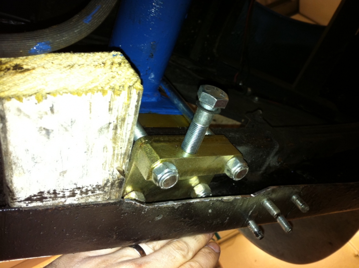
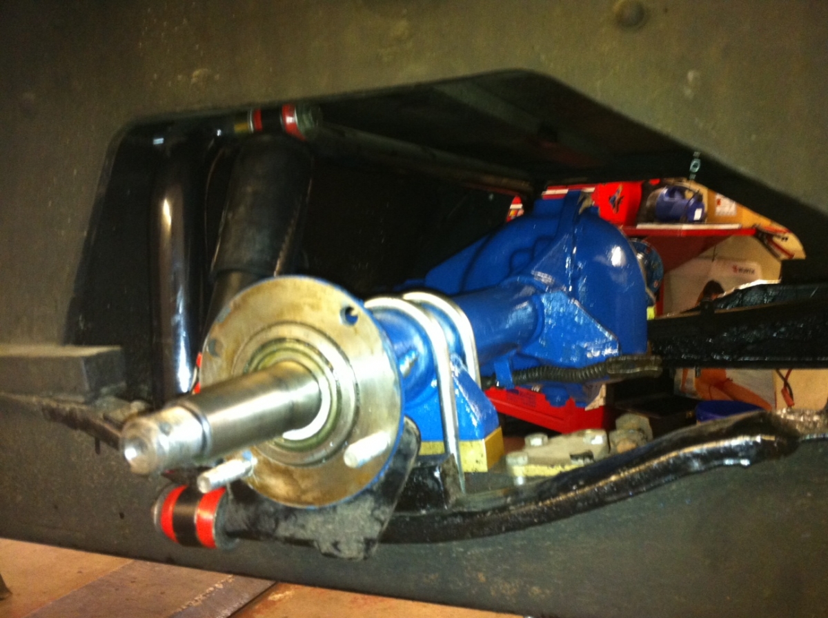
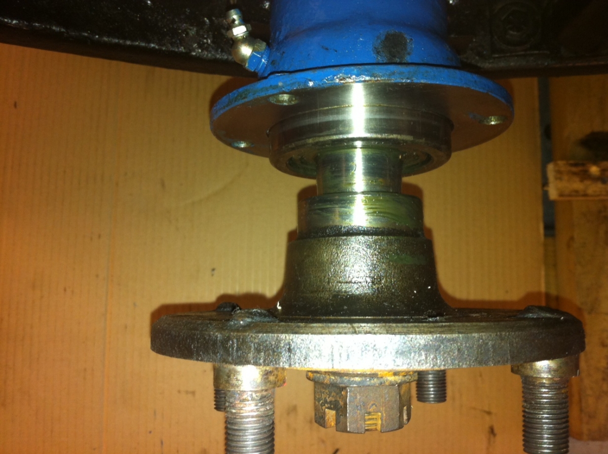
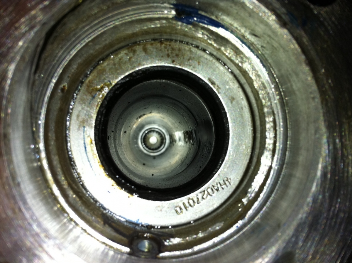
Axle
Having shipped the back Axle up to JB Engineering three weeks ago, I'd not been aware that they were in a 2 week shutdown for charity work. An honourable task to be delayed by and now they are back they are turning around the axle pronto but this only started Tuesday last week when they returned. ETA on this is likely to be next week as well....

Could have the engine and axle back at the same time!!
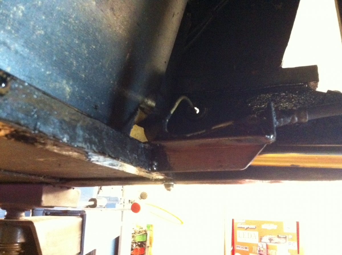
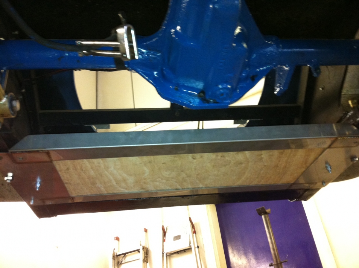
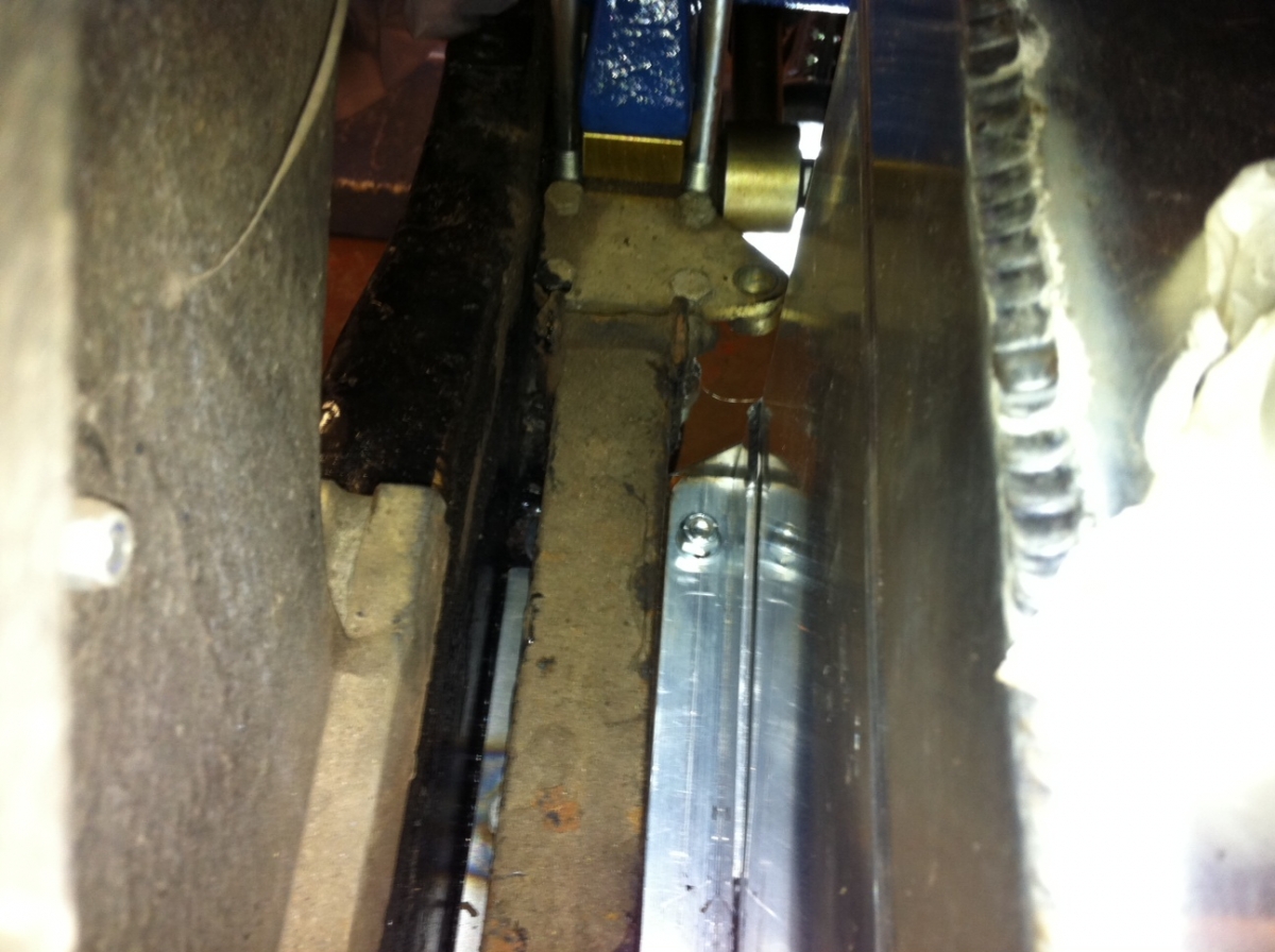
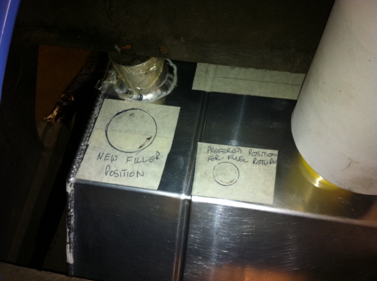
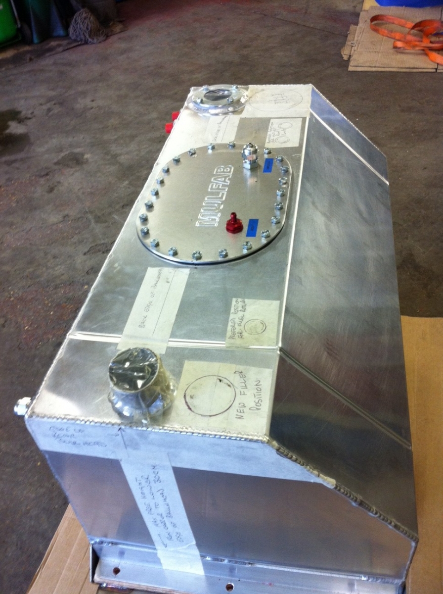
Main Update - Fuel tank
This week we lifted the car back off the trailer and went about fitting the tank. We quickly ran into a few snags. The tank is, in outline "the right shape", just the filler and the fuel sender unit is in the wrong place for our car. Possibly this is suited to an earlier 4/4. Anyhow you can see the problem below.


So... following a quick phone conversation to Peter at Mulfab (who was very accomodating) we spent the rest of the day revising/remarking the layout for a replacement to be made. In addition we designed the swirl pot we need which can be used now for carbs but also in the future if we go injection.

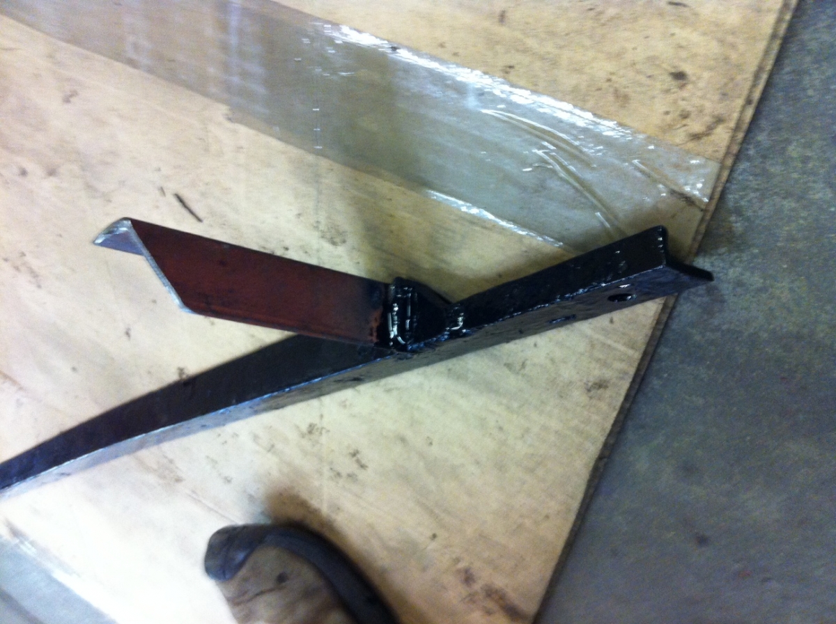
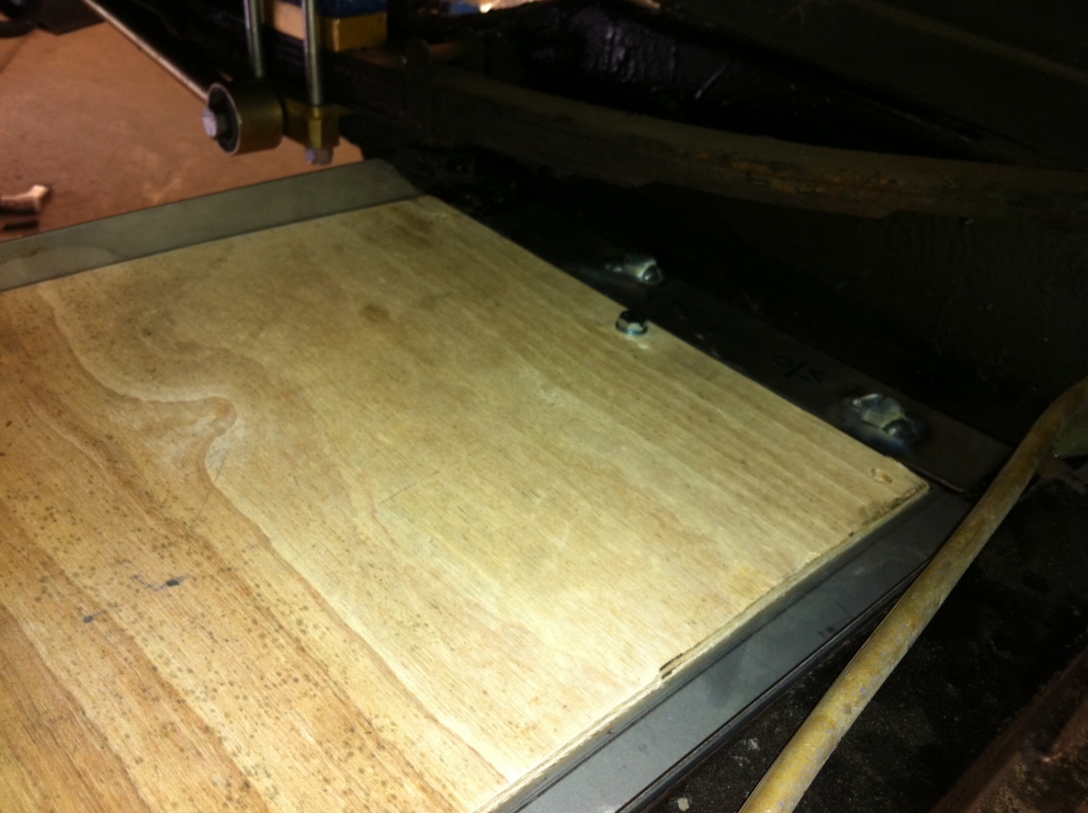
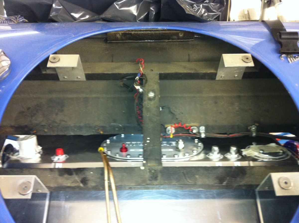
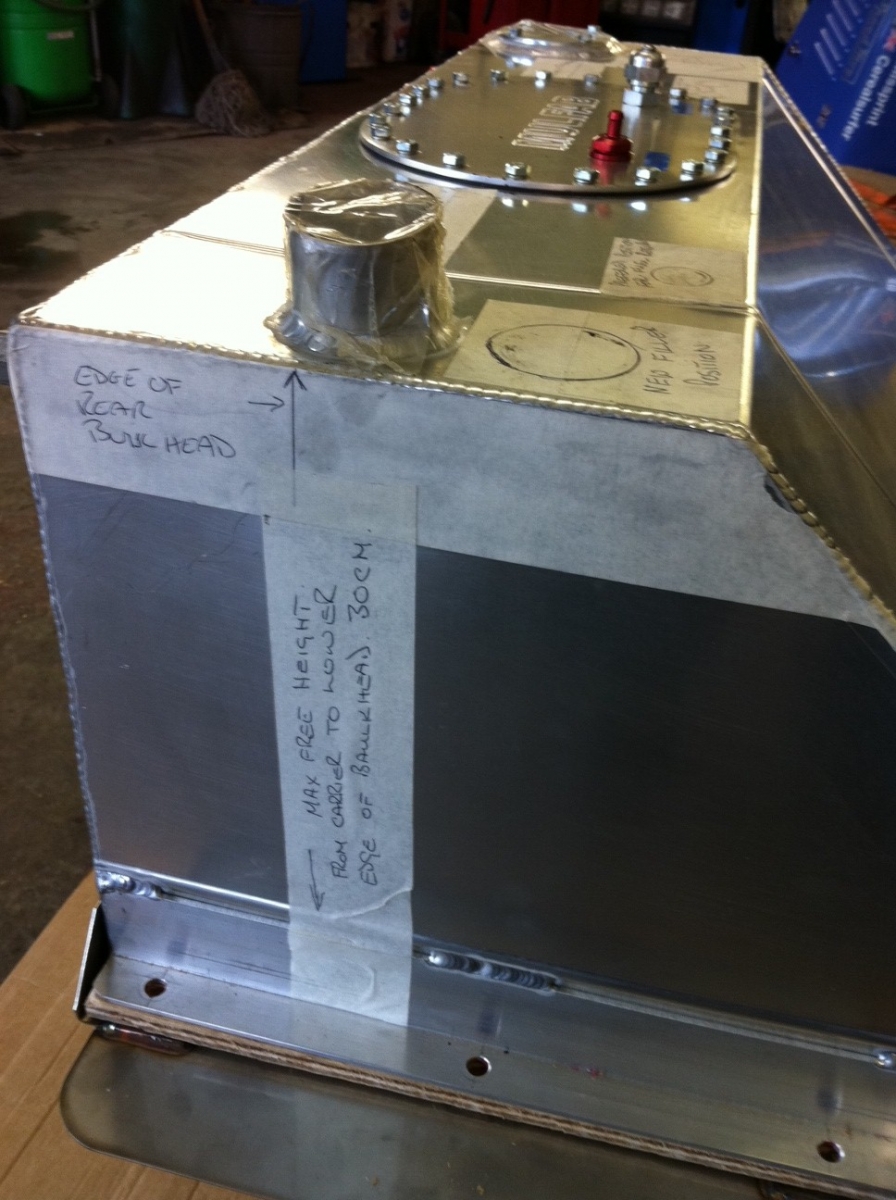
Firstly we needed to validate the outline measurements of the frame. We unbolted the tank from the frame and mounted the frame in position. Using an extended square we measured the limitations of the volume of the space. Once checked we knew that the tank itself would fit into the available hole using the carrier. The problem seemed to be specfically the location of the filler and fuel sender unit. The filler snags the rear frame of the driver tub and there is not enough height for the fuel sender unit to protrude above the tank - as the tank would almost touch the top of the evailable hole.

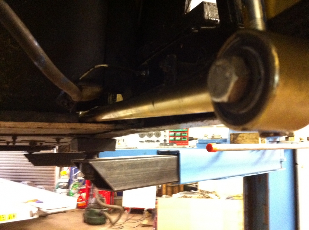
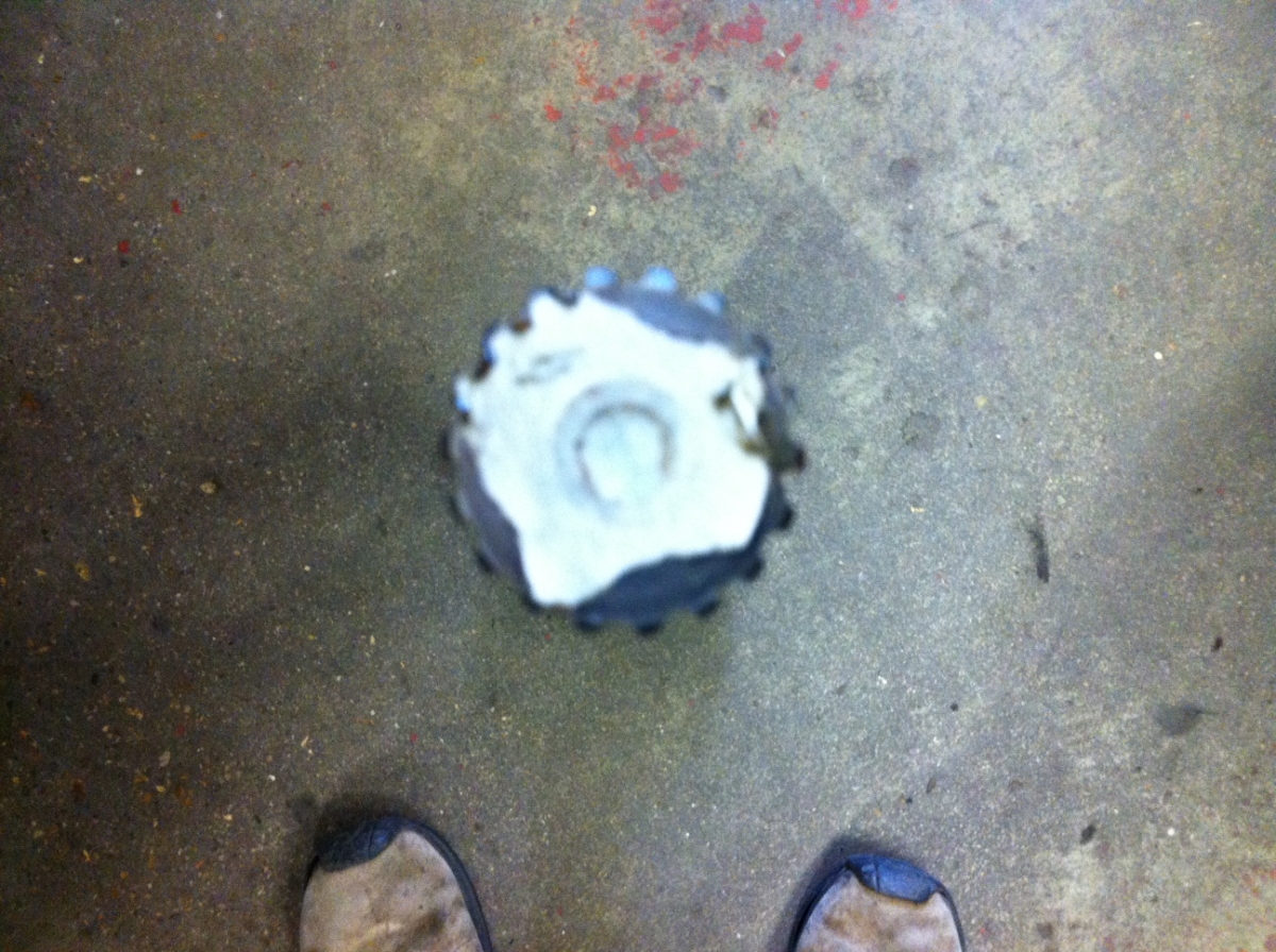
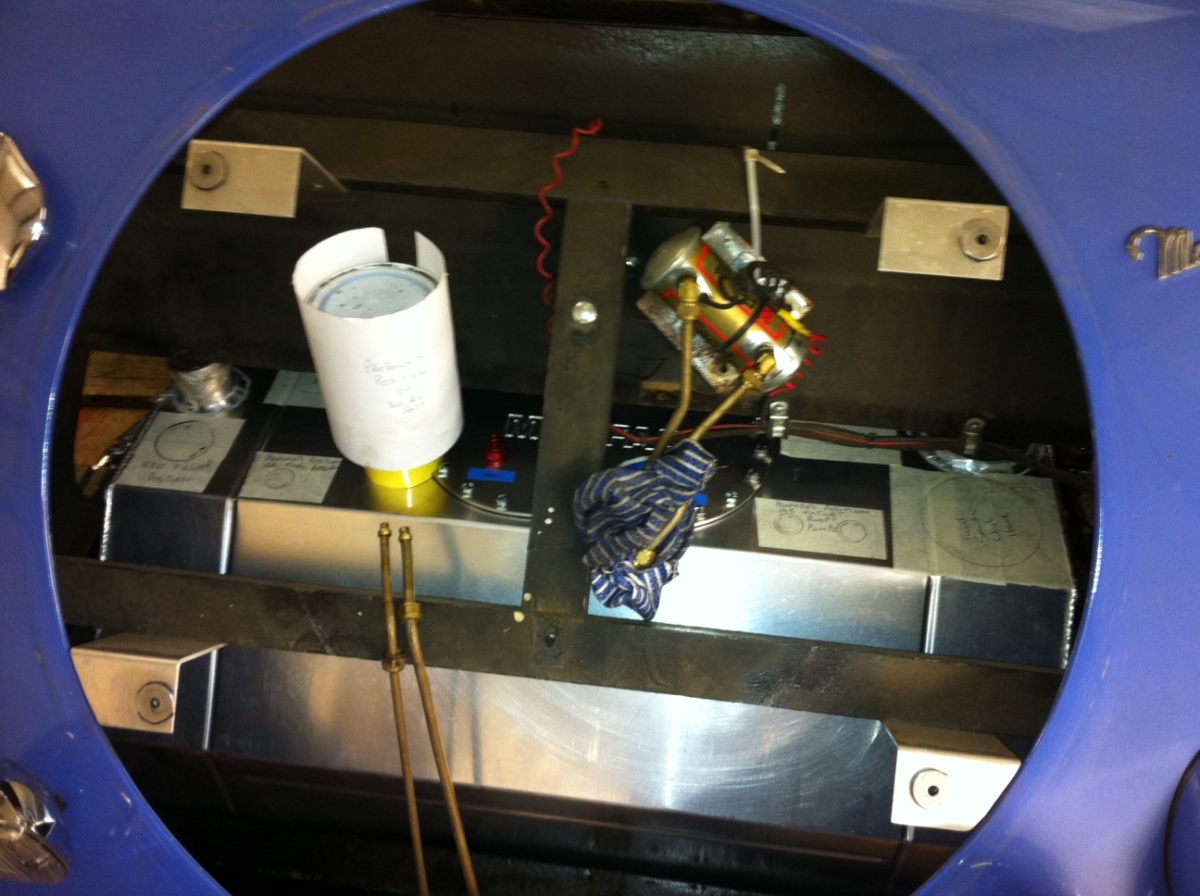
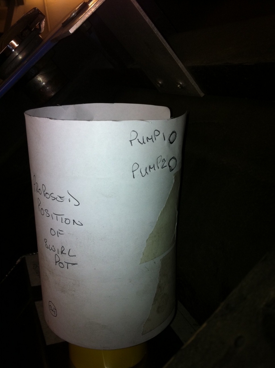
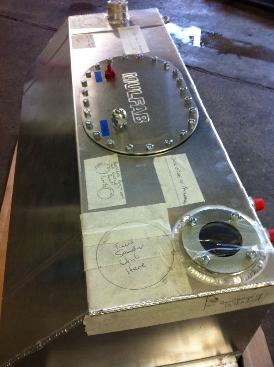
We re-mounted the tank to the frame and held it up on an axle stand and used masking tape to mark out the limitations and revised attachment fitting locations. As it will have to be a new tank, we have also taken the opportunity to mark out ideal locations for the LH and RH fuel pick up connectors and the fuel return connector. These have been marked out to be ideally placed for a rear mounted 1.2lt swirl pot. (the white paper cylinder).


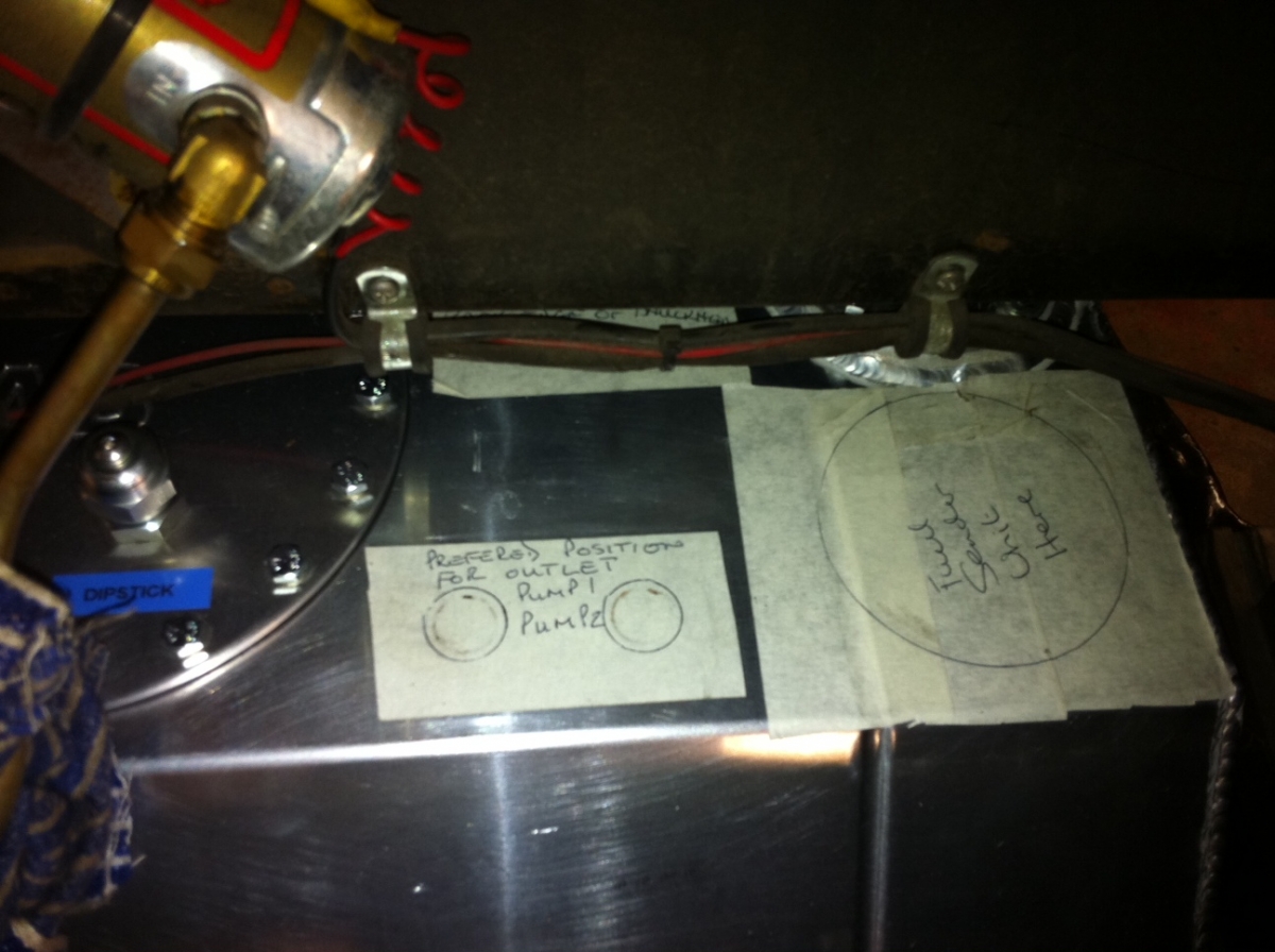
We had been advised to put the swirl pot where the battery used to be, behind the seats, whilst this probably works, it doesn't help accessibility and would require quite a lot of pipe-work..... so we had a look to see where else could work. In the end we've plumped for a swirl pot just over a litre above the LHS of the tank. If we moved the connectors to the top of the tank this would result in much shorter runs of pipework and easy access to both the swirl pot itself and all three of the fuel pumps.

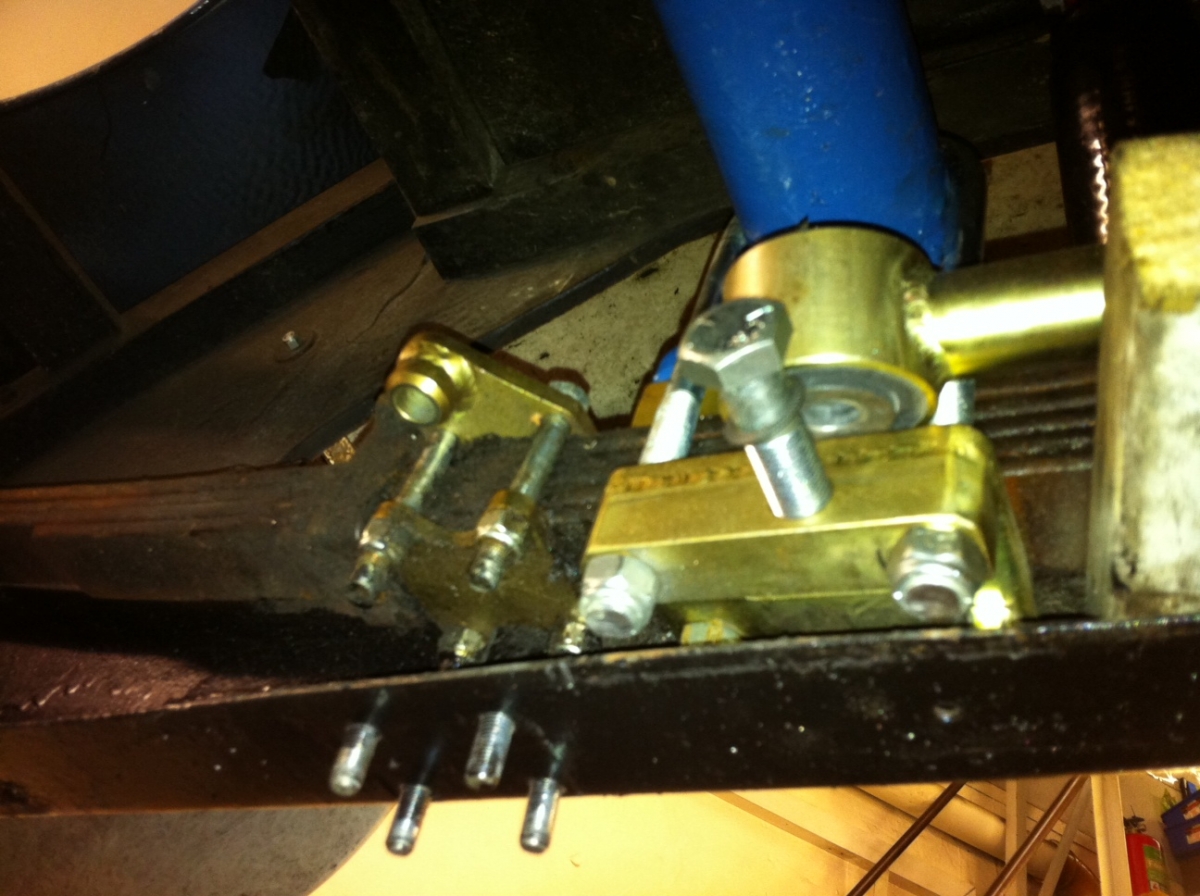
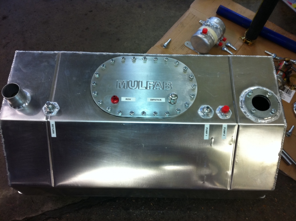
Our proposal is the following:


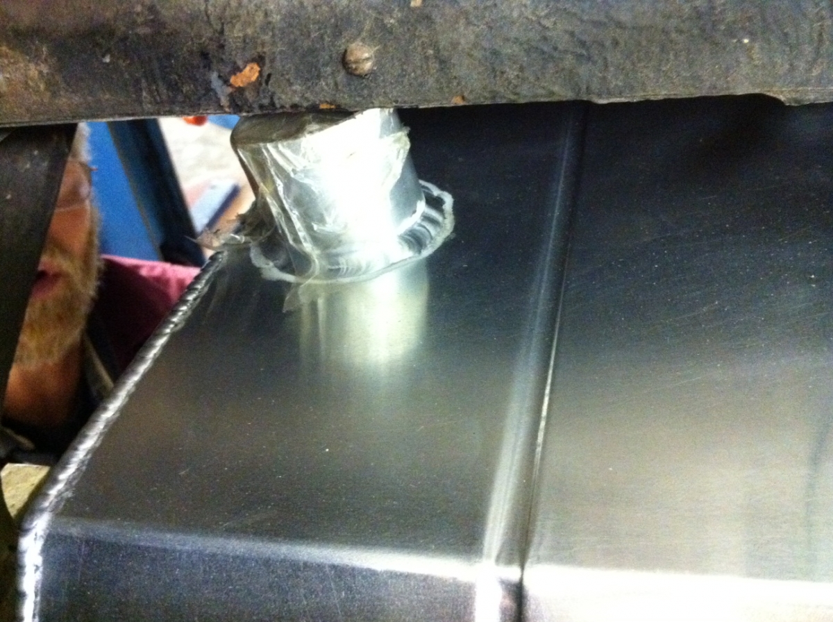
On the RHS at the rear of the swirl pot there are the two lift feeds coming from the RHS top surface of the tank. The output feed to the engine is at the lower front (you can see the existing metal fuel pipes sticking up). The overflow from the top of the swirl pot can feed back down into the return just to the LHS of the swirl pot. The remaining feed that we won't need right now but will do in the future is the injection return. It's the second of the metal fuel pipes sticking up and will also have a feed back into the Swirl pot.

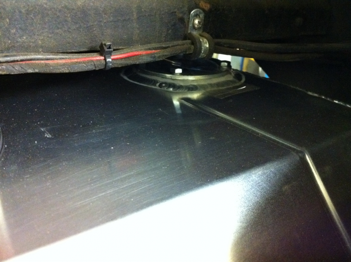
The net result is the following outline:


Next week could be a big week with many things all happening at once, the axle and engine could be ready to return. The Fuel tank shortly after.

We need this to happen as we only have 7 weeks until Race 1 (5/6 May) and once all this hardware is fitted the Librahds exhaust needs making/fitting. Once this has been fabricated the engine can be started for the first time and the 3D ignition ECU and carbs need sorting.

It's looking like things are going to get busy!!! wink


Joined: Oct 2006
Posts: 2,403
C
Talk Morgan Expert
OP Offline
Talk Morgan Expert
C
Joined: Oct 2006
Posts: 2,403
So where did we leave things....!?
Ah yes.. Engine - delayed due to con rods, Fuel Tank - Back to Mulfab for re-manufacture and Axle still with JB Engineering getting sorted out.

So where are we now....?

Mulfab came up trumps... thanks for turning round a great tank in a short space of time along with custom swirl pot! JB Engineering also delivered the axle so we've had a couple of pretty major jobs on. We were aiming to have the engine back this weekend as well but it looks like that is going to be next week now – not that we’re short of things to do, but we are slightly behind plan on getting things turned around, handily I’d planned some slippage time into the programme so we’re still ok for the 5th/6th May first race.

First job on the list was to get the Axle back in, we were also installing anti-tramp bars as well so these jobs can get done at the same time.

The anti-tramp bars require some modification of the heel board to get them tucked through into the cabin to slide onto the front spring mounting bolt.


In the week the seats were removed and the relevant modifications were made to the heel board.


Peter up at Mulfab said that the metal bar across the rear edge of the heel board base needs modification (a notch cut out) so the anti-tramp bars can articulate to the lowest point without bending them. You can see the problem below, clearly the Anti-tramp bar is not going to go low enough to put the bolt through.


In our case this was not enough and in the end decided to remove the cross bar and cut the board back to the heel board and move the cross bar forwards. You can see where we have removed the bar and cut the board back.


Whilst this makes an ideal fix for the Anti-tramp bars it introduces a complication with the brake line mounting bracket which needs to be cut off the cross bar as the flexi pipe is too short otherwise. So what to do there? We decided in the end to cut a small piece of angle and re-weld the brake pipe bracket to keep it in the original position.


With the brake bracket re-welded


The Anti-tramp bars could now be easily mounted appropriately with no interference or potential bending issues.


Onto the Axle

The new Quaife loaded Axle casing was slotted back into the chasses and mounted up with the Anti-Tramp brackets and longer U-bolts. Unfortunately these do not clear the chassis at full articulation so a slight recess needs to be put into the chassis so that the bolts clear ok.


With the recess cut


Joined: Oct 2006
Posts: 2,403
C
Talk Morgan Expert
OP Offline
Talk Morgan Expert
C
Joined: Oct 2006
Posts: 2,403
Once secured into the car the first half shaft was slotted into place, located into the diff end, re-fitting the shims that came off the car and the backing plates and hub re-attached along with AVO adjustable shock. Onwards to the O/S!! (pic shows the back plate removed)


Upon attempting to slide in the O/S half shaft it located ok into the diff splines but then bottomed out, mechanical interference somewhere along the line was not allowing it to fit.


After a bit of head scratching and phone calls, it turns out that whilst the axle is the same the new diff is slightly different in size which means the shims need to be custom spaced upon fitting the half shafts. The reason the N/S had slid in ok is that it had pushed one of the planet gear axle's through to protrude to the O/S, (the shiny dot at the end in the pic below)


hence mechanical interference (can be seen by the circular imprint in the masking tape on the end of the half shaft in the pic below).


So in the end we stripped back down the N/S and tested the imparted theory which allowed the centralisation of the half shafts and diff planet gear axle... so.. now we're stumped as we need 3.5mm worth of shims each side to progress... more head scratching next week to source those!

Next up, the revised tank.. our pencilled up design was as follows;


Mulfab's revision can be seen in it's full glory (we hoped it fitted ok)!


Frst off, we offered up the frame to make sure that went in ok. It did, stage one completed - all's well.


Now onto step two. Getting the tank itself into position, this was a little more tricky. To get the tank in, we lifted the tank into position from the top and held it up then positioned the frame underneath, this is not how it's supposed to be done, the tank is supposed to be mounted to the frame and swung up into position using the rear ledge of the tank frame as the fulcrum on the rear cross member. Our car however has the rear axle locating spacers which put the diff slightly too close to swing the tank up, never mind, we got it into the car anyhow, it just made getting the bolts done up which mount the tank to the frame a little tricky.. smile


Page 5 of 41 1 2 3 4 5 6 7 40 41

Moderated by  TalkMorgan 

Link Copied to Clipboard
Powered by UBB.threads™ PHP Forum Software 7.7.5